Educational Equipments Manufacturer, Exporters & Suppliers - School Educational Equipments Manufacturers & Exporters of Educational Equipments for Lab. Science Lab Products, Teaching Aids, Classroom Instruments, Educational Laboratory
T and Pie Circuit Trainer

Code:EET0156
T and p Network Trainer has been exclusively and attractive designed to demonstrate the significance of image and characteristic impedance of T and p-network. It can be used as a stand alone unit with inbuilt DC power supply. Various scope of learning makes the subject understanding complete.
This trainer includes not only the experimental calculation of image and characteristic impedance but also verifies it by comparing the theoretical values under T and p-networks in a sequential manner. With this, students can learn about importance of Symmetrical and Unsymmetrical networks.
Experiment:
- Study and verification of Image Impedance of Unsymmetrical T-Network
- Study and verification of Image Impedance of Unsymmetrical p-Network
- Study and verification of Characteristic Impedance of Symmetrical T-Network
- Study and verification of Characteristic Impedance of Symmetrical p-Network
Technical Specifications
- Mains Supply : 230 V ±10%, 50 Hz
- DC Power Supply : 5 V, 150 mA
- Adequate no. of patch cords stackable 4mm spring loaded plug length ½ metre.
- Good Quality, reliable terminal/sockets are provided at appropriate places on panel for connections /observation of waveforms.
- Strongly supported by detailed Operating Instructions, giving details of Object, Theory, Design procedures, Report Suggestions and Book References.
Wien Bridge Audio Oscillator

Code:EET0161
Experimental Training Board has been designed specifically for the study of Wien Bridge Audio Oscillator. This Training Board helps to understand the utilization of Audio Oscillator and obtain oscillations at different frequencies.
Practical experience on these boards carries great educative value for Science and Engineering Students.
Object:
To study Transistor Wien Bridge Audio Oscillator:
- To study the main features of the Wien Bridge Audio Oscillator.
- To obtain oscillation of different frequencies by varying R-C.
- To study the frequency response of phase shift network.
Features:
The board consists of the following built-in parts :
- -9V DC at 50mA, IC regulated Power Supply internally connected.
- Variable gang condenser.
- Potentiometer.
- Two PNP transistors.
- Adequate no. of other electronic components.
- Mains ON/OFF switch, Fuse and Jewel light.
- The unit is operative on 230V ±10% at 50Hz A.C. Mains.
- Adequate no. of patch cords stackable from rear both ends 4mm spring loaded plug length ½ metre.
- Good Quality, reliable terminal/sockets are provided at appropriate places on panel for connections/ observation of waveforms.
- Strongly supported by detailed Operating Instructions, giving details of Object, Theory, Design procedures, Report Suggestions and Book References.
- Weight : 3 Kg. (Approx.)
- Dimension : W 340 x H 110 x D 210
Other Apparatus Required:
- A.C. Millivoltmeter
- Audio Frequency Generator
- Cathode Ray Oscilloscope 20 MHz
Phase Shift Audio Oscillator
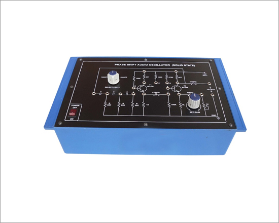
Code:EET0166
Experiment Training Board has been designed specifically for the study of Phase Shift Audio Oscillator. With the help of this Training Board one can understand the utilization of Audio Oscillator and obtain oscillations of different frequencies.
Object:
To study the Phase Shift Audio Oscillator:
- To study Phase Shift Audio Oscillator circuit using a single transistor.
- To study the improved Phase Shift Audio Oscillator circuit using two transistors.
Features:
The board consists of the following built-in parts :
- +9V DC at 50mA, IC regulated Power Supply internally connected.
- Two transistors.
- Three sets of three different values of capacitors selected by a switch for varying frequency.
- Potentiometer for setting gain.
- Adequate no. of other electronic components.
- Mains ON/OFF switch, Fuse and Jewel light.
- The unit is operative on 230V ±10% at 50Hz A.C. Mains.
- Adequate no. of patch cords stackable from rear both ends 4mm spring loaded plug length ½ metre.
- Good Quality, reliable terminal/sockets are provided at appropriate places on panel for connections/ observation of waveforms.
- Strongly supported by detailed Operating Instructions, giving details of Object, Theory, Design procedures, Report Suggestions and Book References.
- Weight : 3 Kg. (Approx.)
- Dimension : W 340 x H 110 x D 210
Other Apparatus Required:
- Cathode Ray Oscilloscope 20MHz
RF (l-C) Oscillators (Hartley's, Colpitt's, Clapp's)
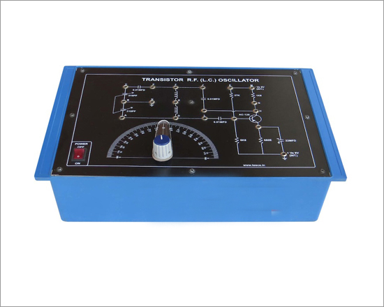
Code:EET0171
Experiment Training Board has been designed specifically for the study of Transistor RF Oscillators such as (i) Hartley's (ii) Colpitt's and (iii) Clapp's Oscillators using L-C.
Object:
To study the following transistor RF oscillators using L-C :
- Hartley's Oscillator
- Colpitt's Oscillator
- Clapp's Oscillator
Features:
The board consists of the following built-in parts :
- 9V DC at 50mA, IC regulated Power Supply internally connected
- Variable gang condenser.
- PNP transistor
- Adequate no. of other electronic components.
- Mains ON/OFF switch, Fuse and Jewel light.
- The unit is operative on 230V ±10% at 50Hz A.C. Mains.
- Adequate no. of patch cords stackable from rear both ends 4mm spring loaded plug length ½ metre.
- Good Quality, reliable terminal/sockets are provided at appropriate places on panel for connections/ observation of waveforms.
- Strongly supported by detailed Operating Instructions, giving details of Object, Theory, Design procedures, Report Suggestions and Book References.
- Weight : 3 Kg. (Approx.)
- Dimension : W 340 x H 110 x D 210
Other Apparatus Required:
Note: Specifications are subject to change. Order Code can be different from Manufacturer's Model No.
Mono-Stable Multivibrator
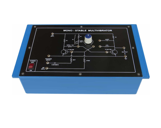
Code:EET0176
Experimental Training Board has been designed specifically for the study of Monostable Multivibrator circuit which is widely used in digital circuits.
Practical experience on these boards carries great educative value for Science and Engineering Students.
Object:
- To study the operation of a Transistor Monostable Multivibrator and to produce a pulse train of varying repetition rate from a square wave input.
- To study the voltage waveforms at various points in the Transistor Monostable Multivibrator circuit.
Features:
The board consists of the following built-in parts :
- ±9V D.C. at 50mA, IC regulated Power Supply internally connected.
- Two NPN transistors.
- One potentiometer.
- Adequate no. of other electronic components.
- Mains ON/OFF switch, Fuse and Jewel light.
- The unit is operative on 230V ±10% at 50Hz A.C. Mains.
- Adequate no. of patch cords stackable from rear both ends 4mm spring loaded plug length ½ metre.
- Good Quality, reliable terminal/sockets are provided at appropriate places on panel for connections/ observation of waveforms.
- Strongly supported by detailed Operating Instructions, giving details of Object, Theory, Design procedures, Report Suggestions and Book References.
- Weight : 3 Kg. (Approx.)
- Dimension : W 340 x H 110 x D 210
Other Apparatus Required:
- Sine Square Wave Oscillator
- Cathode Ray Oscilloscope 20MHz
Regulated Power Supplies
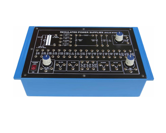
Code:EET0181
Experimental Training Board has been designed specifically for the study of various techniques used for designing transistorised voltage regulated power supplies. A voltage regulated power supply forms an essential part of many electronic equipment.
Practical experience on these boards carries great educative value for Science and Engineering Students.
Object:
- To study half wave rectification.
- To study full wave rectification.
- To study measurement of ripple and ripple reduction methods using the following:
- Capacitor filter.
- Inductor filter.
- Choke input of L.C. filter.
- CLC or p filter.
- To study Zener - diode voltage regulator circuit.
- To study series voltage regulator.
- To study series regulator with current limiting.
- To study error feed-back type series voltage regulator.
- To study the use of Darlington transistor pair for increasing the current capability of series voltage regulator.
- To study a shunt voltage regulator with current limiting.
- To study a shunt voltage regulator with adjustable current limiting.
- To study a 0-9V D.C. continuously variable volt age regulated power supply and measure the following:
- Line regulation.
- Load regulation.
- Ripple factor.
Features:
The board consists of the following built-in parts :
- 9V A.C. at 300mA, Power Supply.
- 0-200mA Electronic load.
- Three NPN and one PNP transistor including a power transistor.
- 4 diodes, 3 Zener diodes, 2 potentiometers, 1 inductor.
- Adequate no. of other electronic components.
- Mains ON/OFF switch, Fuse and Jewel light.
- The unit is operative on 230V ±10% at 50Hz A.C. Mains.
- Adequate no. of patch cords stackable from rear both ends 4mm spring loaded plug length ½ metre.
- Good Quality, reliable terminal/sockets are provided at appropriate places on panel for connections/ observation of waveforms.
- Strongly supported by detailed Operating Instructions, giving details of Object, Theory, Design procedures, Report Suggestions and Book References.
- Weight : 3 Kg. (Approx.)
- Dimension : W 340 x H 110 x D 210
Other Apparatus Required:
- 0-200 mA D.C. Milliammeter
- 0-15VD.C. Voltmeter
- Variac 0-270 Volts at 2 Amp
- Cathode Ray Oscilloscope 20MHz
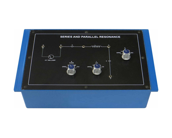
Series and Parallel Resonance
Code:EET0186
Experimental Training Board has been designed specifically for study of Series and Parallel Resonance in LCR Circuits, measurement of Q and dielectric constant of a liquid.Practical experience on these boards carries great educative value for Science and Engineering Students.
Practical experience on these boards carries great educative value for Science and Engineering Students.
Object:
- Series resonance for different values of resistances, capacitances, inductances and plotting of resonance curves.
- Parallel resonance for different values of resistances,capacitances, inductances and plotting of resonance curves.
- Measurement of Q for both series and parallel resonances.
- Measurement of dielectric constant relative permitivity of a liquid.
Features:
The board consists of the following built-in parts :
- Three inductances made on ferrite cores, selectable by a switch.
- Three capacitances with low loss factor, selectable by a switch.
- Three resistances , selectable by a switch.
- Adequate no. of patch cords stackable from rear both ends 4mm spring loaded plug length ½ metre.
- Good Quality, reliable terminal/sockets are provided at appropriate places on panel for connections/ observation of waveforms.
- Strongly supported by detailed Operating Instructions, giving details of Object, Theory, Design procedures, Report Suggestions and Book References.
- Weight : 3 Kg. (Approx.)
- Dimension : W 340 x H 110 x D 210
Other Apparatus Required:
- Decade Audio Frequency Generator
- A.C. Millivoltmeter
- A.F. Millivoltmeter
Note: Specifications are subject to change. Order Code can be different from Manufacturer's Model No.
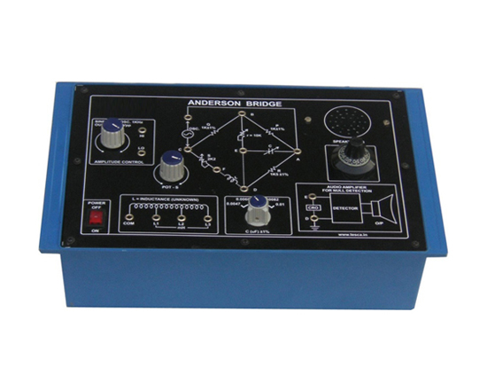
Anderson Bridge
Code:EET0191
Experimental Training Board has been designed specifically for the measurement of inductance of a coil by Anderson Bridge. It includes audio amplifier with speaker for null detection (Instead of head phone) and one KHz sine wave oscillator instead of externally used decade audio frequency generator The board is absolutely self contained and requires no other apparatus.
Practical experience on these boards carries great educative value for Science and Engineering Students.
Object:
- To measure the inductance of a given Coil by Anderson Bridge method.
Features:
The board consists of the following built-in parts :
- Anderson Bridge circuit with arms values
- Potentiometer for varying one arm
- Three different value inductances
- Potentiometer with calibrated dial
- Five capacitors selected by a band switch
- Auio Amplifier with its IC regulated Power Supply
- One KHz Sine Wave Oscillator with its IC regulated Power Supply
- Speaker.
- Mains ON/OFF switch, Fuse and Jewel light.
- The unit is operative on 230V ±10% at 50Hz A.C. Mains
- Adequate no. of patch cords stackable from rear both ends 4mm spring loaded plug length ½ metre.
- Good Quality, reliable terminal/sockets are provided at appropriate places on panel for connections/ observation of waveforms.
- Strongly supported by detailed Operating Instructions, giving details of Object, Theory, Design procedures, Report Suggestions and Book References.
- Weight : 3 Kg. (Approx.)
- Dimension : W 340 x H 110 x D 210
Note: Specifications are subject to change. Order Code can be different from Manufacturer's Model No.
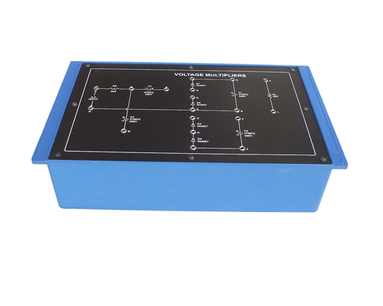
Voltage Multipliers
Code:EET0196
Experimental Training Board has been designed specifically to study the Voltage Multipliers such as Voltage Doubler, Voltage Tripler and Voltage Quadrupler and to determine their regulation characteristics.
Practical experience on these boards carries great educative value for Science and Engineering Students.
Object:
- Full wave Voltage Doubler.
- Half wave Voltage Doubler.
- Voltage Tripler.
- Voltage Quadrupler.
Features:
The board consists of the following built-in parts :
- Four diodes
- Adequate no. of other electronic components.
- Adequate no. of patch cords stackable from rear both ends 4mm spring loaded plug length ½ metre.
- Good Quality, reliable terminal/sockets are provided at appropriate places on panel for connections/ observation of waveforms.
- Strongly supported by detailed Operating Instructions, giving details of Object, Theory, Design procedures, Report Suggestions and Book References.
Other Apparatus Required:
- Variac 0-270 Volts at 2 Amp
- V.T.V.M.
- D.C. Milliammeter 0-100mA
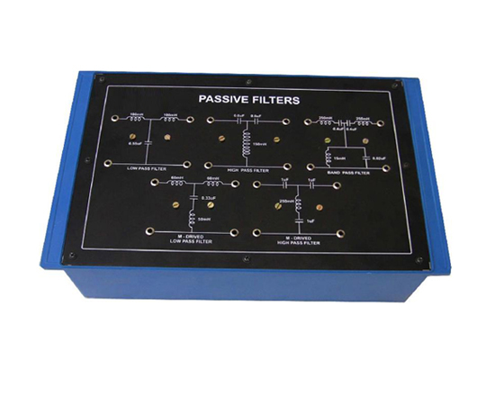
Passive Filters (Constant-K, Low, High and Band M-derived Low & High)
Code:EET0201
Experimental Training Board has been designed specifically to study the various types of Passive Filters and to determine the different constants as well as cut-off frequency of that particular passive filter.
Practical experience on these boards carries great educative value for Science and Engineering Students.
Object:
- Low-Pass constant-K filter
- High-Pass constant-K filter
- Band-Pass constant-K filter
- Low-Pass M-Derived filter
- High-Pass M-Derived filter
Features:
- Different types of Passive Filters
- Adequate no. of other electronic components
- Adequate no. of patch cords stackable from rear both ends 4mm spring loaded plug length ½ metre.
- Good Quality, reliable terminal/sockets are provided at appropriate places on panel for connections/ observation of waveforms.
- Strongly supported by detailed Operating Instructions, giving details of Object, Theory, Design procedures, Report Suggestions and Book References.
- Weight : 3 Kg. (Approx.)
- Dimension : W 340 x H 110 x D 210
Other Apparatus Required:
- Audio Frequency Generator
- A.C. Millivoltmeter
Note: Specifications are subject to change. Order Code can be different from Manufacturer's Model No.
Schmitt's Trigger

Code:EET0206
Experimental Training Board has been designed specifically for the study of Schmitt's transistor binary circuit. Study of this circuit is useful for digital electronics.
Practical experience on these boards carries great educative value for Science and Engineering Students.
Object:
- To find loop gain of the binary circuit and to see the parameters responsible for making the loop gain to 1.
- To adjust the loop gain to be less than 1 and to see linear amplification.
- To adjust the loop gain to be slightly greater than 1 and to observe the switching action.
Features:
The board consists of the following built-in parts :
- 0-12V DC at 50mA, continuously variable regulated Power Supply internally connected.
- Two PNP transistors.
- Adequate no. of other electronic components.
- Mains ON/OFF switch, Fuse and Jewel light.
- The unit is operative on 230V ±10% at 50Hz A.C. Mains.
- Adequate no. of patch cords stackable from rear both ends 4mm spring loaded plug length ½ metre.
- Good Quality, reliable terminal/sockets are provided at appropriate places on panel for connections/ observation of waveforms.
- Strongly supported by detailed Operating Instructions, giving details of Object, Theory, Design procedures, Report Suggestions and Book References.
Other Apparatus Required:
- Decade Audio Frequency Generator
- Decade Resistance Box
- Cathode Ray Oscilloscope 20MHz
Two Stage R-C Coupled Transistor Amplifier

Code:EET0211
Experimental Training Board has been designed specifically for the study of Two Stage R-C Coupled Transistor Amplifier.
Practical experience on these boards carries great educative value for Science and Engineering Students.
Object:
- Study of the overload characteristics of the amplifier.
- Study of the frequency response of the individual as well as the cascade amplifier.
- Calculate the output and input impedance of the individual stages as well as that of cascade amplifier.
Features:
The board consists of the following built-in parts :
- -12V D.C. IC regulated Power Supply internally connected.
- Two PNP transistors.
- Adequate no. of other electronic components.
- Mains ON/OFF switch, Fuse and Jewel light.
- The unit is operative on 230V ±10% at 50Hz A.C. Mains.
- Adequate no. of patch cords stackable from rear both ends 4mm spring loaded plug length ½ metre.
- Good Quality, reliable terminal/sockets are provided at appropriate places on panel for connections/ observation of waveforms.
- Strongly supported by detailed Operating Instructions, giving details of Object, Theory, Design procedures, Report Suggestions and Book References.
- Weight : 3 Kg. (Approx.)
- Dimension : W 340 x H 110 x D 210
Other Apparatus Required:
- Decade Audio Frequency Generator
- A.C. Millivoltmeter
- Decade Resistance Box
Note: Specifications are subject to change. Order Code can be different from Manufacturer's Model No.
Diode & Zener Diode Characteristics

Code:EET0216
Experimental Training Board has been designed specifically for plotting the forward and reverse bias characteristics of a Germanium semiconductor Diode, and a Zener Diode. The board is absolutely self contained and requires no other apparatus.
Practical experience on these boards carries great educative value for Science and Engineering Students.
Object:
- To study and plot the forward & reverse bias characteristics of a Germanium semiconductor Diode.
- To study and plot the forward & reverse bias (breakdown) characteristics of a Zener Diode.
Features:
The board consists of the following built-in parts :
- 0-10V D.C. at 10mA, continuously variable regulated Power Supply with low ripple & hum and integral current limiting resistor.
- D.C. Voltmeter, 65mm rectangular dial, with switch selectable ranges of 1V and 10V.
- D.C. Microammeter, 65mm rectangular dial, with switch selectable ranges of 50 mA and 10mA.
- A Germanium semiconductor Diode mounted behind the panel.
- A Zener Diode mounted behind the panel.
- Adequate no. of other electronic components.
- Mains ON/OFF switch, Fuse and Jewel light.
- The unit is operative on 230V ±10% at 50Hz A.C. Mains.
- Adequate no. of patch cords stackable from rear both ends 4mm spring loaded plug length ½ metre.
- Good Quality, reliable terminal/sockets are provided at appropriate places on panel for connections/ observation of waveforms.
- Strongly supported by detailed Operating Instructions, giving details of Object, Theory, Design procedures, Report Suggestions and Book References.
- Weight : 3 Kg. (Approx.)
- Dimension : W 340 x H 110 x D 210
Note: Specifications are subject to change. Order Code can be different from Manufacturer's Model No.
Transistor Characteristics

Code:EET0221
Experimental Training Board has been designed specifically to study the Transistor input and output Characteristics in different modes i.e.Common Base, Common Emitter and Common Collector. This Training Board is an improved version with Germanium NPN & PNP transistors in addition to Silicon NPN & PNP transistors and four meters. The board is absolutely self contained and requires no other apparatus.
Practical experience on these boards carries great educative value for Science and Engineering Students.
Object:
- Common Emitter Mode.
- Common Base Mode.
- Common Collector Mode.
Features:
The board consists of the following built-in parts :
- Two 0-10V D.C. at 200mA, continuously variable Power Supplies for Base Emitter & Collector Emitter junctions.
- Two D.C. Ammeters, 65mm rectangular dial with switch selectable ranges of 200 mA &10mA.
- Two D.C. Voltmeters, 65mm rectangular dial with switch selectable ranges of 1V and 10V.
- Two silicon (NPN & PNP) transistors and two Germanium (NPN & PNP) transistors.
- Adequate no. of other electronic components.
- Mains ON/OFF switch, Fuse and Jewel light.
- The unit is operative on 230V ±10% at 50Hz A.C. Mains.
- Adequate no. of patch cords stackable from rear both ends 4mm spring loaded plug length ½ metre.
- Good Quality, reliable terminal/sockets are provided at appropriate places on panel for connections/ observation of waveforms.
- Strongly supported by detailed Operating Instructions, giving details of Object, Theory, Design procedures, Report Suggestions and Book References.
- Weight : 5 Kg. (Approx.)
- Dimension : W 412 x H 150 x D310
Note: Specifications are subject to change. Order Code can be different from Manufacturer's Model No.
F.E.T. Characteristics
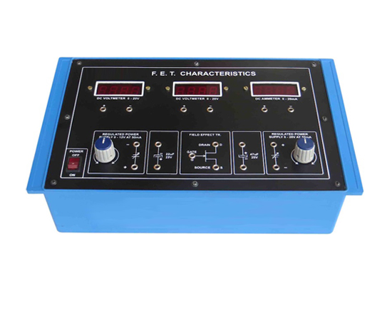
Code:EET0226
Experimental Training Board has been designed specifically to study the characteristics of a Field Effect Transistor. The board is absolutely self contained and requires no other apparatus.
Practical experience on these boards carries great educative value for Science and Engineering Students.
Object:
- Measurement of I DSS.
- Plot the static drain characteristics of FET
(a) Drain Current V/s Drain Voltage Characteristics for different fixed values of VGS.
(b) Drain Current V/s Gate Bias Characteristics for different fixed values of VDS.
- Calculate the FET parameters (drain dynamic resistance r , mutual conductance g , and amplification factor m) at a given operating d m point.
Features:
The board consists of the following built-in parts :
- 0 to 20V D.C. at 50mA, continuously variable Power Supply.
- 0 to 12V D.C. at 50mA, continuously variable Power Supply.
- Two D.C. Voltmeters, 65mm rectangular dial to read 0-20V.04. D.C. Milliammeter, 65mm rectangular dial to read 0-20mA.
- Field Effect Transistor.
- Adequate no. of other electronic components.
- Mains ON/OFF switch, Fuse and Jewel light.
- The unit is operative on 230V ±10% at 50Hz A.C. Mains.
- Adequate no. of patch cords stackable from rear both ends 4mm spring loaded plug length ½ metre.
- Good Quality, reliable terminal/sockets are provided at appropriate places on panel for connections/ observation of waveforms.
- Strongly supported by detailed Operating Instructions, giving details of Object, Theory, Design procedures, Report Suggestions and Book References.
- Weight : 3 Kg. (Approx.)
- Dimension : W 340 x H 110 x D 210
Note: Specifications are subject to change. Order Code can be different from Manufacturer's Model No.
Integrating Differentiating and Clamping Circuits
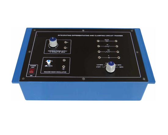
Code:EET0231
Experimental Training Board has been designed specifically to study the Integrating, Differentiating and Clamping Circuits.
Practical experience on these boards carries great educative value for Science and Engineering Students.
Object:
- Study of Integrating Circuit response at 1KHz and 10 KHz for different combinations of R and C.
- Study of Differentiating Circuit response at 1 KHz and 10 KHz for different combinations of R and C.
- Study of series and shunt Clamping Circuits.
Features:
The board consists of the following built-in parts :
- 0-10V D.C. at 20mA, continuously variable Power Supply.
- Square Wave Generator with switch selectable frequency ranges of 1KHz and 10KHz.
- Diode.
- Rotary switch for selection of different values of capacitors
- Adequate no. of other electronic components.
- Mains ON/OFF switch, Fuse and Jewel light.
- The unit is operative on 230V ±10% at 50Hz A.C. Mains.
- Adequate no. of patch cords stackable from rear both ends 4mm spring loaded plug length ½ metre.
- Good Quality, reliable terminal/sockets are provided at appropriate places on panel for connections/ observation of waveforms.
- Strongly supported by detailed Operating Instructions, giving details of Object, Theory, Design procedures, Report Suggestions and Book References.
Other Apparatus Required:
- Cathode Ray Oscilloscope 20MHz
Silicon Controlled Rectifier Characteristics

Code:EET0236
Experimental Training Board has been designed specifically to study the Silicon Controlled Rectifier phase firing and D.C.control characteristics. It is a training aid for advance studies in control circuits.
Practical experience on these boards carries great educative value for Science and Engineering Students.
Object:
- To study the D.C. gate control characteristics (firing characteristics) of a SCR.
- To study and plot the anode current characteristics of a SCR.
- To measure the holding current of a SCR.
- To study the plot the phase firing characteristics of a SCR..
Features:
The board consists of the following built-in parts :
- 0 to 50V D.C. at 50mA, continuously variable Power Supply for Anode.
- 0 to 3V D.C. at 50mA, continuously variable Power Supply for Gate.
- 0-10V A.C. at 50Hz, variable Power Supply for Anode.
- D.C. Voltmeter, 65mm rectangular dial with switch selectable ranges of 1V and 50V.
- D.C. Milliammeter, 65mm rectangular dial to read 0-50mA.
- Silicon Controlled Rectifier .
- Fixed limiting resistances .
- Adequate no. of other electronic components.
- Mains ON/OFF switch, Fuse and Jewel light.
- The unit is operative on 230V ±10% at 50Hz A.C. Mains.
- Adequate no. of patch cords stackable from rear both ends 4mm spring loaded plug length ½ metre.
- Good Quality, reliable terminal/sockets are provided at appropriate places on panel for connections/ observation of waveforms.
- Strongly supported by detailed Operating Instructions, giving details of Object, Theory, Design procedures, Report Suggestions and Book References.
- Weight : 3 Kg. (Approx.)
- Dimension : W 340 x H 110 x D 210
Other Apparatus Required:
- Vacuum Tube Voltmeter
- Cathode Ray Oscilloscope 20MHz
Determination of Energy Band Gap In Semiconductor Diode
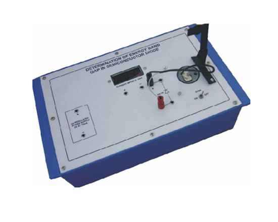
Code:EET0241
Experimental Training Board has been designed specifically for Determination of Energy Band Gap in Semiconductor (P-N Junction Diode) using Temperature dependent of reverse saturation current. The board is absolutely self contained and requires no other apparatus.
Practical experience on these boards carries great educative value for Science and Engineering Students.
Object:
- To draw the characteristics of a P-N junction Diode for reverse saturation current and temperature.
- To determine the Energy Band Gap in a P-N Junction Diode.
Features:
The board consists of the following built-in parts :
- 2V D.C. at 10mA, regulated Power Supply.
- Digital Microammeter, 3½ digits having range 200uA D.C.
- Semiconductor Diode.
- Thermometer 0-110 °C.
- Oven, Electrically heated to heat the Semiconductor Diode.
- Mains ON/OFF switch, Fuse and Jewel light.
- The unit is operative on 230V ±10% at 50Hz A.C. Mains.
- Adequate no. of patch cords stackable from rear both ends 4mm spring loaded plug length ½ metre.
- Good Quality, reliable terminal/sockets are provided at appropriate places on panel for connections/ observation of waveforms.
- Strongly supported by detailed Operating Instructions, giving details of Object, Theory, Design procedures, Report Suggestions and Book References.
Verification of Laws & Network Theorems in DC Circuits Ex
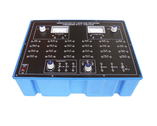
Code:EET0246
Experimental Training Board has been designed specifically for the study & verification of the laws and network theorems in D.C. circuits. The board is absolutely self contained and requires no other apparatus.
Practical experience on these boards carries great educative value for Science and Engineering Students.
Object:
- Verification of Ohm's Law
- To draw the V-I characteristics for studying the D.C. behavior of the following :
- Ideal resistance
- Semiconductor diode
- Zener diode
- Thermistor (NTC Type)
- To verify Kirchoff's current law and voltage law
- Verification of the series & parallel laws for resistances
- Verification of Superposition Theorem
- Study of potential divider.
- Verification of Maximum Power Transfer Theorem
- To verify Thevenin's Theorem and to find equivalent voltage source circuit
- To verify Norton's Theorem and to find equivalent current source circuit
- To study the design of a multimeter
Features:
The board consists of the following built-in parts :
- 0-30V D.C. at 100 mA, continuously variable IC Regulated Power Supply
- +9V D.C. at 100 mA, IC Regulated Power Supply
- +5V D.C. at 100 mA , IC Regulated Power Supply
- D.C. Voltmeter, 65mm rectangular dial with switch selectable ranges of 0.5, 1.5, 25 & 50V
- D.C. Ammeter, 65mm rectangular dial with switch selectable ranges of 0.05, 0.5, 5, 50 & 100mA
- Adequate no. of other electronic components.
- The unit is operative on 230V ±10% at 50Hz A.C. Mains.
- Adequate no. of patch cords stackable from rear both ends 4mm spring loaded plug length ½ metre.
- Good Quality, reliable terminal/sockets are provided at appropriate places on panel for connections/ observation of waveforms.
- Strongly supported by detailed Operating Instructions, giving details of Object, Theory, Design procedures, Report Suggestions and Book References.
- Weight : 3 Kg. (Approx.)
- Dimension : W 412 x H 150 x D 310
Note: Specifications are subject to change. Order Code can be different from Manufacturer's Model No.
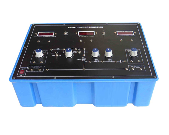
Triac Characteristics
Code:EET0251
Experimental Training Board has been designed specifically to study the characteristics of TRIAC-a Bidirectional Triode Thyristor.
Practical experience on these boards carries great educative value for Science and Engineering Students.
Object:
- To study the gate characteristics of a TRIAC in the following modes :
(a) Mode I+ : i.e. T2 positive with respect to T1 and gate positive with respect to T 1
(b) Mode I- : i.e. T2 positive with respect to T1 and gate negative with respect to T 1
(c) Mode III+ : i.e. T2 negative with respect to T1 and gate positive with respect to T 1
(d) Mode III- : i.e. T2 negative with respect to T1 and gate negative with respect to T 1
- To study the terminal characteristics of a TRIAC in the following modes :
(a) Mode I+ : i.e. T2 positive with respect to T1 and gate positive with respect to T 1
(b) Mode III+ : i.e. T2 negative with respect to T1 and gate positive with respect to T 1
- To study the following applications of TRIAC :
(a) Triac as a static switch (D.C. control).
(b) Control of A.C. with A.C. signal.
(c) To measure the holding current of IH. Triac.
Features:
The board consists of the following built-in parts :
- 0-70V D.C. at 100mA, regulated Power Supply.
- 0-3V D.C. at 30 mA, regulated Power Supply.
- 55 Volt at 100mA, fixed A.C. Supply.
- 7 Volt at 30mA, fixed A.C. Supply.
- Digital Current meter DC 3½ Digit having Dual range of 20mA / 200mA .
- Digital Voltmeter DC 3½ Digit having Dual range of 2V / 200V.
- Digital Current meter DC 3½ Digit range of 200mA .
- TRIAC.
- Three Potentiometers.
- Reset switch.
- Adequate no. of other electronic components.
- Mains ON/OFF switch, Fuse and Jewel light.
- The unit is operative on 230V ±10% at 50Hz A.C. Mains.
- Adequate no. of patch cords stackable from rear both ends 4mm spring loaded plug length ½ metre.
- Good Quality, reliable terminal/sockets are provided at appropriate places on panel for connections/ observation of waveforms.
- Strongly supported by detailed Operating Instructions, giving details of Object, Theory, Design procedures, Report Suggestions and Book References.
Other Apparatus Required:
- Cathode Ray Oscilloscope 20MHz
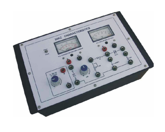
Diac Characteristics
Code:EET0256
Experimental Training Board has been designed specifically to study the characteristics and applications of a DIAC. DIAC is extensively used now a days in power control circuits.
Practical experience on these boards carries great educative value for Science and Engineering Students.
Object:
- To plot V-I Characteristics of a DIAC and study the following :
- Breakover voltage, VBO.
- Negative resistance region.
- VBO symmetry and delta V
- To study the applications of a DIAC as :
- Saw tooth waveform generator.
- Pulse train generator.
Features:
The board consists of the following built-in parts :
- 0-50V D.C. at 50mA, regulated Power Supply.
- 45V A.C. at 50mA, unregulated Power Supply.
- D.C. Voltmeter, 65mm rectangular dial to read 0-50V D.C.
- D.C. Ammeter, 65mm rectangular dial with switch selectable ranges of 200mA and 50mA.
- DIAC.
- Potentiometer and adequate no. of other electronic components.
- Mains ON/OFF switch, Fuse and Jewel light.
- The unit is operative on 230V ±10% at 50Hz A.C. Mains.
- Adequate no. of patch cords stackable from rear both ends 4mm spring loaded plug length ½ metre.
- Good Quality, reliable terminal/sockets are provided at appropriate places on panel for connections/ observation of waveforms.
- Strongly supported by detailed Operating Instructions, giving details of Object, Theory, Design procedures, Report Suggestions and Book References.
- Weight : 3 Kg. (Approx.)
- Dimension : W 340 x H 110 x D 210
Other Apparatus Required:
- Cathode Ray Oscilloscope 20MHz
Note: Specifications are subject to change. Order Code can be different from Manufacturer's Model No.hode Ray Oscilloscope 20MHz
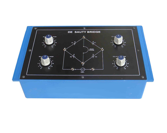
DE-Sauty Bridge
Code:EET0261
Experimental Training Board has been designed specifically to study De-Sauty Bridge and to compare the capacitance of two capacitors.
Practical experience on these boards carries great educative value for Science and Engineering Students.
Object:
- To study the working of a De-Sauty Bridge and to compare the capacitance of two capacitors.
Features:
The board consists of the following built-in parts :
- Two Decade Resistances, each with single dial in steps of 100W total 1kW, to from the two arms of the bridge.
- Two Decade Capacitors, each with single dial in steps of 0.1mF total 1mF, to form the other two arms of the bridge.
- A High Impedance Head Phone, for detecting the null position.
- Adequate no. of patch cords stackable from rear both ends 4mm spring loaded plug length ½ metre.
- Strongly supported by detailed Operating Instructions, giving details of Object, Theory, Design procedures, Report Suggestions and Book References.
- Weight : 3 Kg. (Approx.)
- Dimension : W 340 x H 110 x D 210
Other Apparatus Required:


