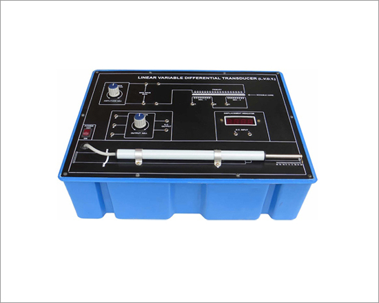
Linear Variable Differential Transducer (L.V.D.T) Trainer
Code:EET2791
Instrumentation trainer has been designed specifically for to study Linear Variable Differential Transducer (L.V.D.T.).The board is absolutely self contained & require no other apparatus.
Practical experience on this set up carries great educative value for Science and Engineering Students.
Study of Linear Variable Differential Transducer (L.V.D.T.)
Features
- One board having the following built in parts.
- ± 12V D.C. at 50mA I.C.regulated Power Supply for Sine wave Oscillator.
- Digital Panel meter 3½ digits range 200mV.
- Detector circuit with output adjustment pot.
- 9 pin male connector.
- Transducer : Linear variable differential transducer (L.V.D.T.).
- Range : ± 20 mm. (Accuracy ± 1 mm, ± 1 Digit)
- Moving action : 6 wires,spring loaded type axial.
- Mains ON/OFF switch and fuse.
- Adequate no.of patch cords stackable 4 mm spring loaded plug length ½ metre.
- Good Quality, reliable terminal/sockets are provided at appropriate places on panel for connections /observation of waveforms.
- Strongly supported by detailed Operating Instructions, giving details of Object, Theory, Design procedures, Report Suggestions and Book References.
- Weight : 4 Kg. (Approx)
- Dimension : W 412 x H 150 x D 310
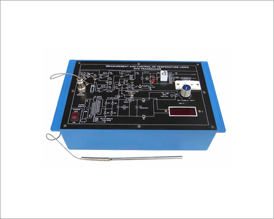
Measurement and Control Of Temperature Using RTD Transducer
Code:EET2796
Industrial Control Transducer has been designed specifically for measurement and control of temperature using RTD Transducer. The board require other apparatus like heater and beaker. Practical experience on this set up carries great educative value for Science and Engineering Students.
Measurement and control of temperature using RTD transducer
Features:
- ±12V DC at 100 mA, IC Regulated Power Supply
- 6 V DC at 100 mA, IC Regulated Power Supply
- Four Op-Amp. ICs
- Relay 12 V DC, one change over
- One NPN transistor
- 31/2 digits display panel meter, to display temperature in °C
- RTD sensor with 3 pin connector
- One switch for setting temperature on one side and to read actual temperature on other side
- Potentiometer to control temperature
- AC mains socket to connect load whose temperature is to be controlled
- Adequate no. of other Electronic Components
- Mains ON/OFF Switch and Fuse 400 mA
- The unit is operative on 230V ±10% at 50Hz AC Mains
- Good Quality, reliable terminal/sockets are provided at appropriate places on panel for connections/ observation of waveforms
- Strongly supported by detailed Operating Instructions, giving details of Object Theory, Design, Procedures, Report Suggestions
- Weight : 4 Kg. (Approx)
- Dimension : W 412 x H 150 x D 310
Other Apparatus Required:
- Heater 1000 W 230V
- Beaker
Load Cell Demonstrator
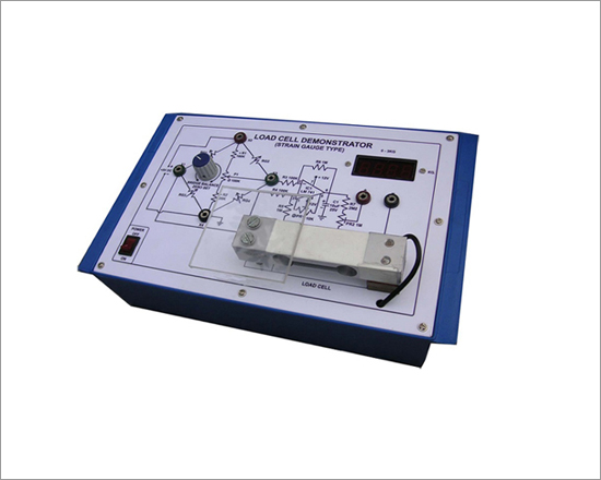
Code:EET2801
Looking to the recent requirement of educational institutions, we have developed. Load Cell Demonstrator. It shows digital display of measured weight. Practical experience on this board carries great educative value for Science and Engineering Students.
To study Load Cell Demonstrator
The board consists of following built in parts
Features:
- ± 12V D.C. at 100mA, I.C.regulated Power Supply
- 5V D.C. at 100mA, I.C.regulated Power Supply
- IC for comparision of Load Signal
- Load Cell of 3kg with 200mV output
- DPM of 3½ digit display for 3kg
- Adequate no.of other electronic components
- Mains ON/OFF switch and fuse
- The unit is operative on 230V ±10% at 50Hz A.C.Mains
- Good Quality, reliable terminal/sockets are provided at appropriate places on panel for connections/ observation of waveforms.
- Strongly supported by detailed Operating Instructions, giving details of Object, Theory, Design procedures, Report Suggestions and Book References.
- Weight :4 Kg.(Approx)
- Dimension : W 340 x H 110 x D 210
Optical Transducer Trainer
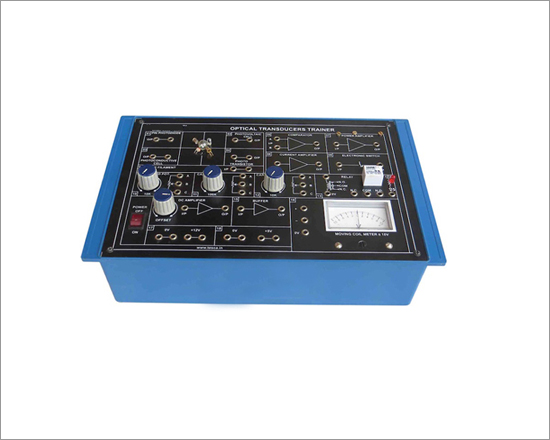
Code:EET2806
Optical and Temperature transducers play a very important role in today's industrial and domestic applications. Optical and Temperature Transducers Trainers are unique in design because each cover study of 4 different type transducers. Experiments covering fundamental characteristics of transducers & study of transducer controlled switching alarm systems can be performed with these trainers. These trainers comes with exhaustive manuals covering theory and experimental procedures for conducting experiments.
Features
- Characteristics of Filament Lamp
- Characteristics of Photovoltaic Cell
- Characteristics of Photoconductive Cell
- Characteristics of Photo transistor
- Characteristics of PIN Photo diode
- Light Controlled Switch System
Technical Specification:
- Transducers : 4Nos.
- Photoconductive Cell
- Photovoltaic Cell
- Photo transistor
- PIN Photo diode
- Light Source : Filament Lamp
- Signal Conditioning Circuitry
- Power Amplifier
- Current Amplifier
- DC Amplifier
- Cooperator
- Electronic Switch
- Buffer
- Input Circuits :Rotary & Slide Potentiometers
-
- Signal Conditioning Circuitry
- Moving Coil Meter
- Relay
- Buffer
- Interconnections : 4 mm banana sockets>
- Mains Supply :100 - 240V, 50Hz.60Hz on request.
- Power Consumption :2VA(approx).
- Accessories : Line cord, Manual, Set of Patch Cords.
Ultrasonic Digital Distance Meter
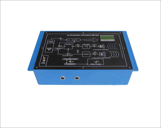
Code:EET2811
Ultrasonic Digital Distance Meter has been designed specifically for measuring distance between 0.3 metre to 3 metres. The measuring distance is shown on a 3 digit liquid crystal display LCD. Practical experience on this set up carries great educative value for Science and Engineering Students.
To measure unknown distance between 0.3 metre to 3 metres
The setup is complete in all respect and requires no other apparatus. Practical experience on this setup carries a great educative value for Science and Engineering students.
Features:
The unit consists of following built in parts :
- Ultrasonic (Transmitter)
- Ultrasonic Receiver
- A timing and time reference section
- A counter with 3½ digit liquid crystal display LCD
- Adequate no. of other electronic components
- The unit is operative on 9V DC Battery cell
- Good Quality, reliable terminal/sockets are provided at appropriate places on panel for connections/ observation of waveforms
- Strongly supported by detailed Operating Instructions, giving details of Object, Theory, Design procedures, Report Suggestions and Book References
- Weight : 4 Kg. (Approx)
- Dimension : W 340 x H 110 x D 210
Other Apparatus Required:
Temperature Measurement Tutor Using AD - 590

Code:EET2816
Has been designed specifically to study the Temperature Measurement Tutor using AD - 590.The board is self contained and require no other apparatus. Practical experience on this board carries great educative value for Science and Engineering Students.
To study the Characteristic of AD - 590
Features:
The unit consists of following built in parts :
- ± 12V D.C.at 100mA, I.C.regulated Power Supply internally connected
- 3-30V D.C.at 50mA, IC regulated Power Supply
- 30V D.C.at 600 mA.Unregulated power supply for oven
- Oven for heating AD-590
- Two AD-590, One for study of characteristic and one for maintaining the set temperature
- 31/2 digits digital panel meter for temperature display
- 31/2 digits digital panel meter with switch selection to read voltage range 0 - 200V and to read current 0 - 1999uA
- Potentiometer to set the temperature
- Adequate no.of other Electronic Components
- Mains ON/OFF switch and Fuse
- Weight : 4 Kg (Approx.)
- Dimension :W 340 x H 110 x D 210
- The unit is operative on 230V ± 10% at 50 Hz A.C.mains
- Adequate no.of patch cords stackable 4 mm spring loaded plug length ½ metre
- Good Quality, reliable terminal/sockets are provided at appropriate places on panel for connections /observation of waveforms
- Strongly supported by detailed Operating Instructions, giving details of Object, Theory, Design procedures, Report Suggestions and Book References
D.C. Motor Speed Control Trainer
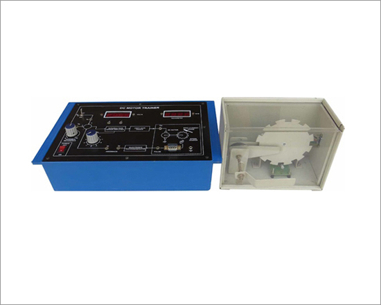
Code:EET2821
D.C motor Speed control trainer built around a small permanent magnet D.C. motor is designed to bring out the salient features of such a system. Facilities are available to directly measure the principal performance features of the speed control system, viz, steady state error and load disturbance rejection, as a function of the forward path gain. In addition the experimental work involves the determination of the motor transfer function and the characteristics of the tachogenerator.An important feature of the unit is the built-in absolute speed measurement through photo diode pick-up from a slotted disk followed by a frequency counter.Variable loading of the motor is achieved by a built-in eddy current brake.
Features:
- Closed loop motor speed control with eddy current brake
- Compact system-no mechanical hassles
- Photo diode speed sensor
- Digital speed display
Experiments:
- Effect of loading on the speed of the motor in the open loop
- Steady state error variation with forward gain
- System time constant variation with forward gain
- Effect of forward gain on disturbance rejection
- Determination of the motor transfer function and tachometer characteristics
Technical Specifications
- Speed control of a 12V,4W permanent magnet D.C.motor
- Speed range : 0 to 2500 rpm (typical)
- Photo diode based speed sensing
- 4-digit speed display in rpm
- Electronic tacho generator for feedback
- Separate unit for motor in a see through cabinet
- Smooth, non-contact eddy current brake for loading
- Built-in 3½ digit DVM for signal measurements
- Built-in IC regulated internal power supply
- The unit is operative on 230V ±10% at 50Hz A.C.Mains
- Adequate no.of patch cords stackable from rear both ends 4 mm spring loaded plug length 50 cm.
- Good Quality, reliable terminal/sockets are provided at appropriate places on panel for connections/observation of waveforms
- Strongly supported by detailed Operating Instructions, giving details of Object, Theory, Design procedures, Report Suggestions and Book References
- Dimension : W 425 x H 190 x D 290
Other Apparatus Required:
- Cathode Ray Oscilloscope 20MHz.
Control System Lab
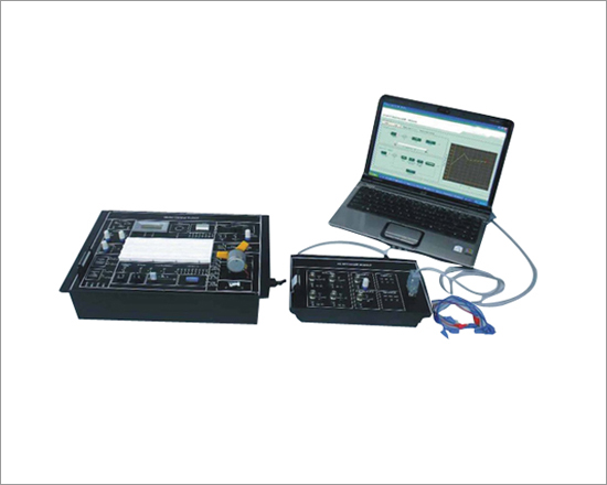
Code:EET2826
Control System Lab explores students & industry professional to the fundamentals of Control System. It demonstrates, how one device can be used to manage, command, direct or regulate the behavior of other system. Sequential Control, Linear Control is also well explained in the trainer.
Control System Lab has sensors like Temperature sensor, Light sensor, DC motor, Filament lamps, IR sensor and many more which can be used for the study of Control system. There is a wide range of experiments which can be performed on the trainer. Application software for Interfacing with PC increases range of experiments.
Features:
- Open loop Control system
- Close loop Control system
- Feedback concept
- Servo motor control
- DC motor control
- Speed control
- Light intensity control
- Temperature Control
- V/F & F/V conversion
- LED bar display
- Bread board for circuit design
- User can design & develop own circuits
- On board DC supply
- PC interface for open loop & Close loop control
- PC based Frequency counter
- PC based DC voltmeter
- Real time graphical representation
- User friendly software
- Exhaustive course material & references
Experiments that can be performed
- To study and observe Voltage to Frequency converter
- To study and observe Frequency to Voltage converter
- To study and implement Light intensity control using PWM method
- To study and observe Characteristics of Photoconductive Cell (LDR)
- To study and implement Motor speed and input characteristics
- To study and implement Bidirectional motor speed control
- To study and implement tachogenerator using F/V converter
- To study and implement Motor control using PWM method
- To study and implement DC Motor Control-Open Loop
- To study and observe DC Motor Control-Close Loop
- To study and implement Temperature Control-Open Loop
- To study and observe Temperature Control-Close Loop
- To study and implement Light intensity Control-Open Loop
- To study and observe Light intensity Control-Close Loop
Accessories Include
- Patch Cord 8" ( 2 mm to 1 mm ) 4 nos.
- Patch Cord 12" 8 nos.
- 5 Pin DIN cable 1 no.
- PC Interface Module 1 no
- Software CD 1 no.
- Mains Cord 1 no.
- Operating Manual 1 no.
- Dust Cover 1 no.
Technical Specifications
- DC Motor : 12 VDC
- Servo Motor : 5 VDC
- Temperature Sensor : 10 mV / °C
- Light Sensor : Photo Conductive Cell (LDR)
- Light Source : Tw o n u m b e r s o ffilament lamps
- V/F : For 0 - 5 V output is 0 - 50 KHz (approx.)
- F/V : For 0 - 50 KHz output is 0 - 5 V (approx)
- PC based Analog Inputs : 4 Inputs with 0 to 5 V / 0 to 10 V
- PC based Analog Output : 1 Output with 0 to 5 V / 0 to 10 V
- PC based Digital Inputs : 3 Inputs
- PC based Digital Outputs : 3 Outputs
- PC based DC Voltmeter : 0 to 10 V range
- PC based Frequency counter : 0 to 6 MHz (square wave)
- DPM : Rang 0-20 Vdc
- De-Bounced Switch : Monostable (5 V output)
- Buzzer : 5 V operated
- Switches : IR Switch, DIP selector switch
- Clock : 0-50 KHz (approx)
- Power Supply : 230 V ±10%, 50 Hz
- Test Points : 28
- Dimension (mm) : W 365 D 265 H 120
- Weight : 4 Kg (approx)
Mini Process Control Demonstrator
Code:EET2831
In this modern era, instrumentation & control engineering have major share for the industrial growth, whilst process control is a vital concept of it. The functionality and complexity of process control have been increased.
Mini Process Control Demonstrator endows students and industry professionals to understand the concepts and working of thermal process control which enables them to learn advance and more complex thermal process; and contribute in the growth of instrumentation arena. It formulates students to accumulate, develop and practice the fundamentals of thermal process control.
Mini Process Control Demonstrator has sensors like temperature sensor, liquid level sensor, level indicators. It has safety measures such as emergency shutdown and overheat protector. There is a wide range of experiments that can be performed on the trainer. It also has computer interfacing with real time graphical analysis which helps to perform mathematical calculations required to state stability of process using methods like root locus, bode plot, etc. This feature increases the scope of doing research and implementing ones innovative ideas related to thermal process control.
Study of process with two position controller, PID controller and optionally with PLC.
Technical Specifications
- Vessel Capacity : 2 Litres
- Temperature Measurement : RTD (-99 to 850°C)
- Heater : 230 V AC
- Temperature Range : from room temperature to 100°C
- Temperature Indicator : 0 to 850°C
- Control Valve : Manually Operated
- Stirrer : 0 or 5 V DC
- Level Sensor : 0 or 5 V DC
- Indicators : Level Indicators Stirrer Indicator Heater Indicator
- Relay Action : Forward for Cooling and Reverse for Heating
- PID Controller : Ha rdwa r e ba s ed & Computer based
- ON/OFF Controller : Ha rdwa r e ba s ed & Computer based
- Computer Interface : USB
- Analog Input : One (0 to 5 V DC)
- Digital Input : Two (TTL)
- Digital Output : Two (TTL)
- Switches : Two (TTL)
- Signal Conditioning : Amplifiers with gain of 1 and 10
- PC Based Temperature Indicator : 0 to 100°C
- Power Supply : 230V ± 10%, 50 Hz (others on request)
Pneumatic Trainer
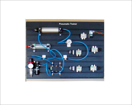
Code:EET2836
Pneumatic Trainer explores students & industry professionals to the basic principles of pneumatics and compressed air devices. It tells, how components manage, command, direct or regulates pneumatically. All types of pneumatic controls are explained in the trainer.
Pneumatic Trainer has pneumatic components which can be used for study of Basics of Pneumatics. There is a wide range of experiments which can be performed on the trainer.
A complete set up with Air Compressor
Mounting panel for Pneumatic components
Different pneumatic arrangements; includes Control Diagrams
Sequential & Linear Pneumatic Control
Understanding of Industrial Pneumatic Components
Pneumatic Safety Awareness
Exhaustive course material & references
Features
- Air Compressor
- Pressure Range : 0 to 150 psi and 0 to 10 Kg/cm
- Supply : 230 V AC
- Motor Type : Single Phase
- Motor Power : 0.5 HP
- RPM : 1440
- Tank capacity : 5 Liters
- Components
- Single Acting Cylinder : Stroke length of 54 mm 2 Operating Pressure range (0.5 - 8 Kg/cm )
- Diameter - 32 mm
- Port size - 1/8 inch
- Double Acting Cylinder : Stroke length of 100 mm 2 Operating Pressure range (0.5 - 8 Kg/cm )
- Diameter - 32 mm
- Port size - 1/4 inch
- FRL Unit : Operating Pressure 115 psi, Filter size 25 micron
- 2 Solenoid Valves : 3/2 type, Operating Pressure range (1.5 - 8 Kg /cm )
- Operating voltage +24V DC
- 2 Pressure Gauge : Reads (0 - 150 psi and 0 - 10 Kg/cm )
- Manifold : 8 ports
- ounting Panel Dimension: 500 W ' 660 D ' 15H
Scope of Learning
- Study of the operation of a Single Acting cylinder.
- Study of the operation of a Double Acting cylinder.
- Observation of the piston movement of a Single Acting cylinder manually by using Push button.
- To study manual control of piston movement of double acting cylinder.
- To study of Pilot control of a Single Acting cylinder piston movement.
- To study of Pilot control of a Double Acting Cylinder piston movement.
- To study manual sequencing control (A+A-) of double acting cylinder.
- To study manual sequencing control (+A+B-A-B) of double acting cylinder.
- To study manual sequencing control (+A-B+A-B) of double acting cylinder.
- To study manual sequencing control (-A+B+A-B) of double acting cylinder.
- To study manual sequencing control (-A-B+A+B) of double acting cylinder.
- To study combined sequencing of a Single acting cylinder and a Double acting cylinder by using 3/2 solenoid valve.
- To control the combined sequencing of a Single acting cylinder and a Double acting cylinder by using 3/2 & 5/2 Hand Lever valve.
Temperature Transducer Trainer
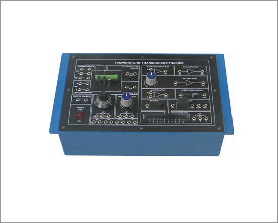
Code:EET2841
Features
- Self contained trainers
- Each with 4 different Transducers
- Study of Transducer controlled switching / alarm systems
- On board signal conditioning circuitry
- Built-in DC power supply
- Functional blocks indicated on-board Mimics
- Fully documented Student Workbook andl Operating Manual with each trainer
Experiments that can be performed
- Characteristics of IC temperature Sensor
- Characteristics of NTC Thermistor
- Characteristics of NTC Bridge Circuit
- Characteristics of Platinum RTD
- Characteristics of K type Thermocouple
- Temperature Controlled Alarm System
... and many more
Technical Specifications
- Transducers : 4 Nos.
- N.T.C. Thermistor
- Platinum R.T.D.
- K Type Thermocouple
- IC Temperature Sensor
- Heating Element : Wirewound resistance 47 ? , 7 ? Signal Conditioning Circuitry :
- Instrumentation Amplifier
- X100 Amplifier
- DC Amplifier
- Comparator
- Electronic Switch
- Input Circuits : Rotary & Slide Potentiometers Output Circuits :
- Interconnections : 4mm. banana sockets
- Power Supply : 220 V ±10 %, 50 Hz / 60 Hz on request
- Power Consumption : 2 VA (approx.)
- Dimensions (mm) : W 340 × D 240 × H 105
- Accessories : Line cord, Manual, Set of patch cords.
Relay Control Trainer
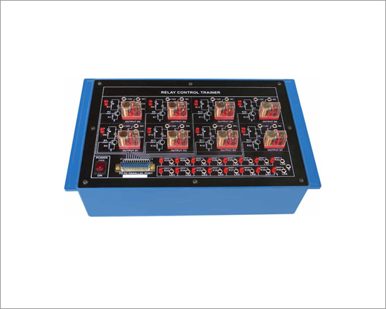
Code:EET2846
With the rapid progress in computer technology and theirapplications, these computers can be used as dedicated controllersfor a variety of uses: turning on/off lights or other devices aroundthe home, office, laboratory or factory come to mind. All that isneeded is the interface to connect it to the real world. This Kitprovides both the hardware and the software to do this.
It is a unique Trainer which controls 8 electromechanical relaysusing parallel-port of Personal Computer. The hardware kit plugsin directly to the parallel port of the computer. It carries 8 relays.Each relay is switched on or off by output data (8 bits) sent byparallel port of the computer. Thesoftware provides a graphicaluser interface to control relay operations, their control sequences With LED indication and simulations.
Features
- Controlling of eight relays (DC 12V) with LED indication
- Relay control and simulation facility using software
- Controlling relay sequences using software
Technical Specifications
- Eight identical switched relays (DC 12V) O/E/N-58-06-1C
- Power input positions to the relays using 3 pole terminal blocks
- DB25 connector to the parallel port of a PC
- Protection of Parallel port on PC in case of accidentaldisconnection
- Diode protection for transistors
- Power Supply : 220 V ±10 %, 50 Hz / 60 Hz on request
- Power Consumption : 2 VA (approx.)
- Relay controlling software -Windows 9x/XP Version
- Dimensions (mm) : W 440 × D 240 × H 105
Pressure Transducer Trainer
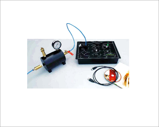
Code:EET2851
Pressure Transducer Trainer is designed to learn concept of Pressure measurement. It helps students & industry professionals to understand operation of Pressure Transducer in detail. Built-in On/Off Controller is also provided with audio & visual indicators. It also has a PC interface through USB for more interactive understanding of transducer characteristics. User can also take a direct printout if desired.
Pressure Transducer Trainer has a wide range of experiments with user friendly software.
Technical Specifications
- Pressure Transducer : 0 to 100 psi, Differential input
- Pressure Gauge : 0 to 150 psi
- Pressure Vessel : 0 to 100 psi
- Safety Valve : 0 to 100 psi
- Valves : Non-returning valve & Manual vale
- Hoses : 1.5 m
- V-I Specification : 0 to 5 VDC input, 4 to 20 mA output
- Buzzer Indicator : 5VDC
- Pressure Vessel : 0 to 100 psi
- LED Indicator : 5V DC
- Digital Voltmeter : 0 to 10V
- PC Interface : USB
- Power Supply : 220 V+ 10%, 50 Hz
- Differential Input Pressure Transducer
- Precise Signal conditioning
- Self-contained and easy to operate
- Data acquisition using USB
- Sensitive, Linear, Stable & Accurate
- Functional blocks indicated on board mimic
- On board Digital Voltmeter
- On board Indicators; Buzzer & LED
- On board On/Off Controller
- Graphical representation
- User friendly software
- Exhaustive course material & references
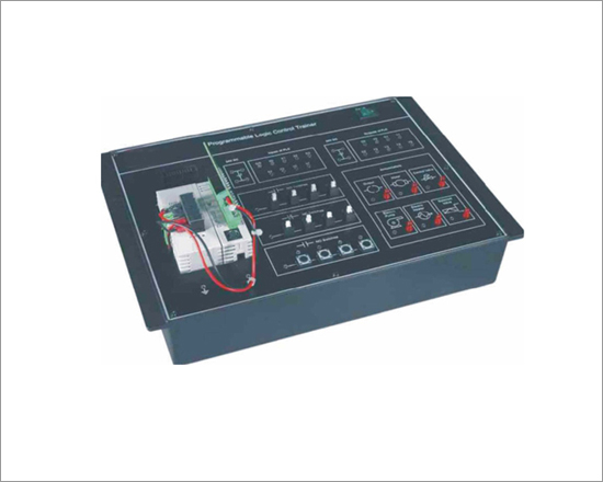
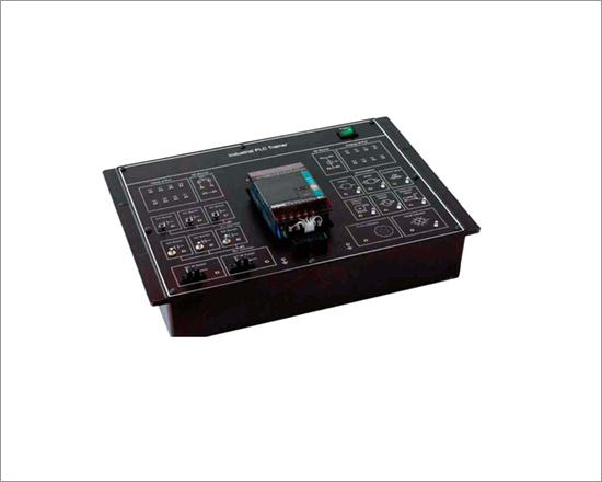
PLC Trainer
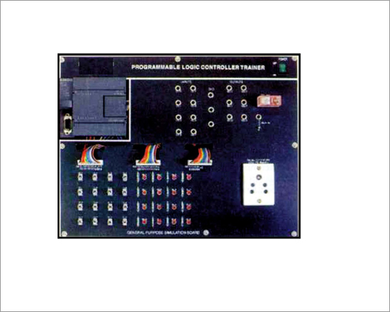
Code:EET2856
In today's the importance of PLC has rapidly increased with growing demand for training in this area. The standard packages for PLC are module experiment PCB, power supply, programming and operating software. Optional accessories includes digital and analog expansion modules.
Technical Specifications
- Siemens CPU Type 222 224 226
- Digital Input 8 14 24
- Digital Output 6 10 16
- Analog adjustments
- (8-bit resolution) 1 2 2
- Program Size (words) 2048 4096 4096
- General Purpose Simulation PCB
- Toggle Switches 8 16 24
- LED Display 8 12 16
- Internal Memory (bits) : 256 Boolean Execution speed
- Sec. Per instruction : 037ms/ instruction
- PC/PPI Cable Rate : 9.6, 19.2 & 187.5 K baud
- No. Of ports : 1
- Interface : RS485
- Input Voltage : 24VDC
- Output Voltage : 5V DC
- Potentiometer : 4 Nos.
General:
- Power Supply : 220V ± 10%, 50/60Hz, 5VA
- Dimensions (mm) : W 450< H 113, D 280
- Weight : 5.5 Kgs (Approx)
- Included Accessories : Programming & Operating software manual, PC/PPI interface cable, Software CD, Softcopy of Siemens Manual
- Optional Accessories : Digital input & Digital output, Analog expansion modules.
- Exclusive and attractive designed panel
- Micro PLC from Siemens
- Ladder, L|STL & FBD Languages
- PC Based programming
- Ready to use Configuration
- Programming and operating software
- Soft copy of PLC introduction and tutorials
- Choice of PLC and expansion module
- Expandable input/output
- Experiment PCB with Switches, LED's and potentiometers
- Built-in DC power supplies
- Ready experiments
- Operating Manual
- Application Software for car parking, washing machine, Vending Machine, Tank Level Control & Elevator Control
Experiments that can be performed
- Drink Machine. (For cola, lime and lemon)
- Car Parking. (For three cars)
- Tank Level Control. (High level, low level and empty)
- Step Sequence. (Use of timer at different time interval)
- How to create delays. (Off delay, pulse, extended pulse)
- Light Intensity variation. (Intensity variation with the help of digital processing)
- Motor Control. (Stepper motor clockwise anticlockwise directional control
- Digital Electronics Design (combinational, sequential & control logic)
- Process Control Unit. (B&C)
- Batch Processing (B&C)
PLC Trainer
Code:EET2861
Features
- Micro PLC from Delta
- On board NO/NC switches
- Sample of Annunciator given on board
- Most user friendly, most powerful instruction sets
- High execution speed
- PC Based Programming
- Soft copy of PLC introduction and Tutorials
- Choice of PLC and expansion module
- Built-in power supplies
- Ready experiments
- Operating Manual
Technical Specifications :
- DELTA CPU Type : DVP-14SS
- Digital Input : 8
- Digital output : 6
- Program size : 3792Steps
- Expansion module : Not expandable
- Toggle Switches : 8
- Latch Switches : 4
- LED Display : 6
- Boolean Execution speed Sec. per instruction : 0.33 ìs / Sequential instruction in average
- Interfacing : RS232
- No. of ports : 1
- Input voltage : 24 V DC
- Output voltage : 5 V DC
- General
- Power Supply : 220 V ±10 %, 50 Hz / 60 Hz on request
- Power Consumption: 5 VA (approx.)
- Included Accessories:
- Operating Manual 2. Interfacing cable 3. Software CD
- Soft copy of Manual 5. Patch Cords
PLC Trainer
Code:EET2866
PLC Trainer is an ideal tool to study the working of PLC's used for industrial applications. The trainer has been designed to demonstrate the application of PLC in the area of 1. Wiring of PLC with different inputs and outputs. 2. Switches like Latch, NO/NC toggle, NO/NC IR can beconnected as an input to the PLC. 3. PLC can drive annunciator which has valves, motor, pump, visual indicator and audio indicators according to the input of PLC.
Features
- Micro PLC from Fatek
- On board NO/NC switches
- On board IR switches
- Sample of Annunciator given on board
- Most user friendly, most powerful instruction sets
- PC Based Programming
- Soft copy of PLC introduction and Tutorials
- Choice of PLC and expansion module
- Built-in power supplies
- Ready experiments
- Operating Manual
- Ready to use Application boards
Technical Specifications
- FATEK CPU Type FBs-14 MA FBs-20 MA
- Digital Input 8 12
- Digital output 6 8
- Program size(Words) 2048 4096
- Expansion module Not expandable Expandable
- General Purpose Simulation PCB
- Toggle Switches 3 3
- Latch Switches 3 3
- IR Switches 2 2
- LED Display 7 7
- Boolean Execution speed Sec. per instruction : 0.33 ìs/Sequential instruction in average
Interfacing : Rs232,
- No. of ports : 1, Input voltage : 24 V DC
- Output voltage : 5 V DC
General
- Power supply : 220 V ±10%, 50 Hz / 60 Hz on request ,
- Power Consumption : 5 VA (approx.)
Included Accessories
- Operating Manual.
- Interfacing cable.
- Software CD.
- Soft copy of FATEK Manual.
- Patch Cords.
- Optional Accessories: Analog expansion module (4 inputs and 2 outputs).
Water Level Control - Optional PLC Application Board
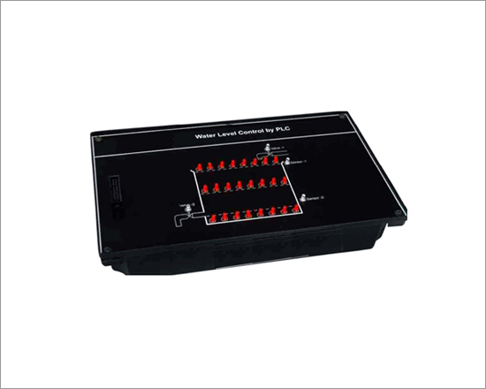
Code:EET2871
Water Level Control - Optional PLC Application Board
Water level control enables students and practicing engineers to gain invaluable practical experience of the principles and application of programmable logic controllers. The object is to connect and program an external programmable logic controller to monitor and control the level of water in a tank system. Water level controlling is shown with the help of LEDs. The apparatus is connected with output of PLC. Two valves for filling and draining water are shown, for indicating ONOFF condition of valve LED is used. Filling of tank indicated by two sensors, positioned
to sense maximum and minimum water levels of tank.
Technical Specifications:
- Interface : 20 pin FRC cable needed with PLC (ST2401 A / B / C)
- Input pin voltage : 24 V DC when particular i/p is activated from PLC
- Output pin voltage : 5 V DC when particular o/p is activated from PLC
- Power supply : From PLC Trainer
Elevator Control - Optional PLC Application Board
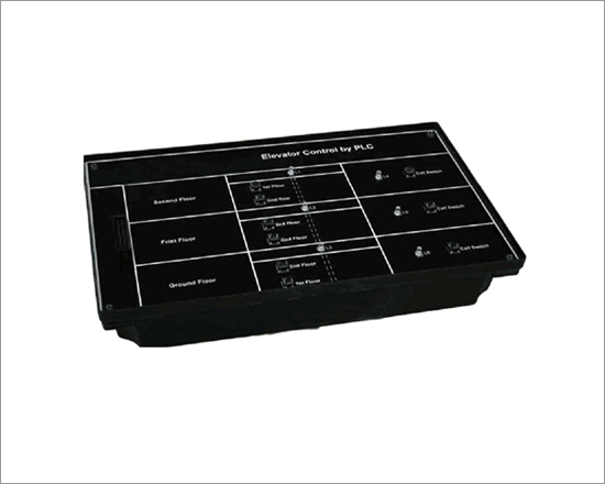
Code:EET2876
Elevator Control - Optional PLC Application Board
Elevator Control by PLC enables students and practicing engineers to gain invaluable practical experience of the principles and application of programmable logic controllers. The object is to connect and program an external programmable logic controller to monitor and control elevator system. Elevator controlling model is shown with the help of switches & LEDs. The apparatus is connected with input and output of PLC. Three floors as shown on board, switches are used to call and go to the desired floor. LEDs are indicating on which floor the elevator is present. The elevator model board is made in such a way that student can understand how elevator can be control by using PLC and also student gets familiar with how inputs and outputs of PLC are used.
Technical Specifications
- Input pin voltage : 24 V DC when particular i/p is activated from PLC
- Output pin voltage : 5 V DC when particular o/p is activated from PLC
- Power supply : From PLC Trainer
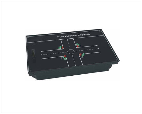
Traffic Light Control - Optional PLC Application Board
Code:EET2881
Traffic Light Control - Optional PLC Application Board
Traffic light control enables students and practicing engineers to gain invaluable practical experience of the principles and application of programmable logic controllers. The object is to connect and program an external programmable logic controller to monitor and control the traffic light system. Traffic light controlling is shown with the help of LEDs. The apparatus is connected with output of PLC. Four way traffic is automatically controlled by PLC roads which meeting at a circle.
Technical Specifications
- Interface : 20 pin FRC cable needed with PLC (ST2401 A / B / C)
- Input pin voltage : 24 V DC when particular i/p is activated from PLC
- Output pin voltage : 5 V DC when particular o/p is activated from PLC
- Power Supply : From PLC Trainer
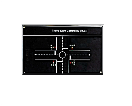
Traffic Light Control - Optional PLC Application Board
Code:EET2886
Traffic Light Control - Optional PLC Application Board
Traffic Light Control enables students and practicing engineers to gain invaluable practical experience of the principles and application of programmable logic controllers. The object is to connect and program an external programmable logic controller to monitor and control the Traffic Light Control system. Traffic light controlling is shown with the help of LEDs. The apparatus is connected with output of PLC. Four ways traffic is automatically controlled by PLC roads which meeting at a circle.
Technical Specifications:
- Interface : 20 pin FRC cable needed with PLC (ST2401B/C).
- Input pin voltage : 24VDC when particular i/p is activated from PLC
- Output pin voltage : 5VDC when particular o/p is activated from PLC
- Power supply : From PLC trainer
Conveyor Belt - Optional PLC Application Board
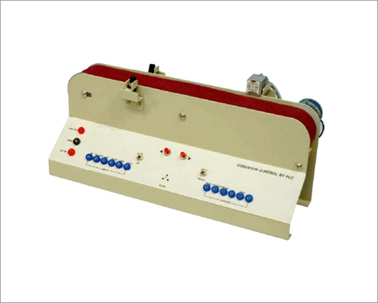
Code:EET2891
Conveyor Belt - Optional PLC Application Board
Conveyor Control by PLC enables students and practicing engineers to gain invaluable practical experience to understand the use of Conveyors and its control using PLC in the process industries. The object is to connect and program an external PLC (Programmable Logic Controller) to monitor & control a process which uses a conveyor.
It is a single stage unit having a conveyor along with mounting assembly of two sensors. Two types of boxes travel on conveyor one is of metal & other is of non-metal, one sensor is for counting & other is for detecting the type of box. Unit has inputs to PLC like On/Off, auto/manual control and some extra inputs are also given. Similarly the outputs of PLC are available on the panel. One buzzer is also given as annunciator. Note: It can only be used in combination with PLC Trainer 52014, 52015, 52016 and 52018, 52019.
Features:
- Real time conveyor control by PLC
- Product sorting
- Works on both Auto/Manual mode
- Provision for user to expand the number of sensors
- Exhaustive course material & references
- Optional application boards
Technical Specifications
- Digital Input pin voltage : + 24 V DC when particular I/P are activated for PLC
- Digital Output pin voltage : + 5 V DC when particular O/P is activated from PLC
- IR Sensor : + 24 V DC output
- Proximity Senso : + 24 V DC output
- DC Motor : + 5 V DC
- Latch Switches : Two
- Power Supply : From PLC trainer (+ 24 V DC & + 5 V DC)
- Interface : 2mm patch cords needed along with PLC trainer
PID Controller Trainer
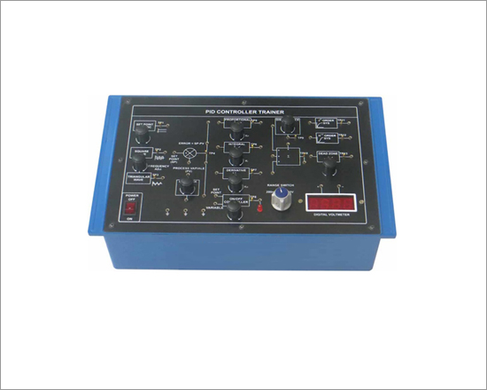
Code:EET2896
In control system there are different types of controller. Study of two-position mode as ON/OFF controller and continuous controller modes as PID controller is a very important part of control engineering. To have a basic idea and practical hands on controllers our PID Trainer has been designed to be used by student to investigate the fundamental principles of PID by applying different signals to it.
With PID controller trainer student can study two position mode as ON/OFF controller and continuous controller modes as P-control mode, I-control mode, D control mode, PI-control mode, PD - control mode and PID control mode. This modes of controller can be performed individually and also with different combinations in open loop and close loop system. With this trainer user can easily understand the difference between the different modes of controllers used. Square wave, triangular wave generator and variable DC supply as set point is given on board and disturbance generator is provided. Effect of PID can be seen on first order system and second order system in open loop and close loop system, which is given on the board.
Features:
- Proportional, Integral and Derivative functions can be checked on same board ( configurable as P,I, D, PI, PD, PID )
- ON/OFF controller
- Square and triangular wave with variable frequency for testing PID
- Variable DC for set point
- Error detector
- Ist order system & IInd order system
- In built power supply
- Dead zone and disturbances generator
- Built-in 3½ DVM for DC measurement
- Test point at varies block to measure and observe the signals.
- Manual describing working of trainer along with detailed experiment descriptions
Technical Specifications
- Proportional Band : 5% to 55%.
- 10 msec to 110 msec
- 1 msec to 11 msec
- ON/OFF controller : ON = 12 V, OFF = -12 V
- On board Generator : Square wave & triangular wave
- Generator of 0 -156 Hz, Two Variable DC +6 V,+10 V
- Power Supply : 220 V ±10 %, 50 Hz / 60 Hz on request
- Power Consumption : 1.6 VA (approx.)
Digital Control System
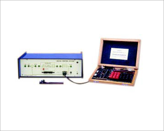
Code:EET2901
Digital Controller implementation on mP - kit
Simple Op-amp based analog plant
CRO display of response
Design and test new algorithms
Introduction
Digital control of industrial processes has become very important today because of the advantages it offers and the increased availability of inexpensive computing power of microprocessors. The principal advantages include fixed hardware with complete software flexibility and the feasibility of implementing integration and differentiation on extremely slow varying signals. On the other hand digital controllers have some drawbacks also such as errors due to the processes of sampling and reconstruction, computational errors caused by finite wordlength, truncation, register overflow, as well as the de-stabilisation effects of sampling. A clear understanding of all these aspects is of great value to a student of control engineering. In the present unit a second order transfer function, simulated with operational amplifiers and passive components, has been chosen as the process to be controlled. This results in a well behaved and near perfect linear process which gives a highly predictable performance and enables the student to concentrate on the design and evaluation of the controller. The digital controller consists of a 8085 based microprocessor kit with analog-to-digital and digital-to-analog interface. The dynamic ranges of the variables in the whole system and that of the built-in square wave test input signal are made compatible. The step response may be displayed and studied using an external measuring CRO. Software supplied with the system resides in a 8K EPROM. This consists of P, P-I and P-I-D algorithms in which the three gains may be selected out of 16 levels each. All arithmetic calculations are performed in 16-bits and are also available to the user as subroutines. Detailed information and listing of the software is included in the literature, besides suggestions and procedures for conducting experiments. Also included are typical results of some experiments with their theoretical descriptions. Further, the user may write his own programs to implement additional algorithms and study their responses.
Experiments
- Identification of the controlled process
- Study of sampling period variation
- Designing P, PI, PD and PID controllers
- Advanced algorithms implementation
A.C. Servomotor Study
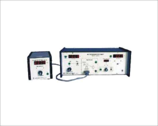
Code:EET2906
Two phase a.c. servomotor is one of the very important electromechanical actuators having applications in the area of control systems. The studyof its operating principle and features form a part of the first course on automatic control systems inelectrical engineering curriculum. It's smallsize, low inertia and almost noise and frictionless operation makes the a.c. servomotor particularly attractive in aircraft and spacecraft applications. The characteristics of an a.c. motor is usually non-linear. To simplify the analysis a linearized model is developed. The experimental work revolves around determination of the parameters of the motor and thus its transfer function. Important subsystems of the unit includes,
(a) an integrated speed sensor with 4-digit display in r.p.m.
(b) an electrical loading system to compute torque
(c) a time-constant measurement circuit with 3-digit display in milli seconds
(d) a three step a.c. source with built-in r.m.s. voltmeter, and
(e) a digital voltmeter on the panel for load measurement
The unit has been designed such that expensive equipment like storage CRO is not needed. Also the hassle of direct torque measurement usingspring balance etc. is avoided by linearization of the motor characteristics analytically.
Features:
- Torque computation through electrical Loading
- Determination of motor parameters - inertia and friction
- Digital display of time Constant
- Transfer function evaluation
- 2-phase a.c. servomotor - 12V/ 50Hz per phase
- Small generator for loading
- 4-digit speed display
- 3-digit time constant display
- 3½ digit r.m.s. voltmeter
- 3½ digit d.c. panel meter
- Voltage regulated internal supplies
- Detailed literature with sample result
Experiments
- Inertia and friction parameters
- Time constant
- Transfer function