Analog Electronics Trainer


Measurement of Capacitance byWien Bridge

Code:EET0376

Experimental Training Board has been designed specifically for the study of Wien Bridge and by which one can evaluate the unknown value of capacitance.

Practical experience on this board carries great educative value for Science and Engineering Students.

Object:

  • To measure the capacitance by Wien Series Bridge.
  • To measure the capacitance by Wien Parallel Bridge.

Features:

The board consists of the following built-in parts :
  • ±12V D.C. at 100mA, IC regulated Power Supply internally connected.
  • 1 KHz Sine Wave Oscillator.
  • Audio Amplifier and speaker for null detection.
  • Three decade resistances, single dial in steps of 100 Ohm, Total 1K each, to form arms of a bridge.
  • Decade resistance, Two dials of 10 Ohm & 100 Ohm, total 1100 Ohms to form arms of bridge.
  • Decade Standard Capacitances, selectable by a band switch to form the one arm of the bridge.
  • Unknown capacitor and adequate no. of other electronic components.
  • Mains ON/OFF switch, Fuse and Jewel light.
  • The unit is operative on 230V ±10% at 50Hz A.C. Mains.
  • Adequate no. of patch cords stackable from rear both ends 4mm spring loaded plug length ½ metre.
  • Good Quality, reliable terminal/sockets are provided at appropriate places on panel for connections/ observation of waveforms.
  • Strongly supported by detailed Operating Instructions, giving details of Object, Theory, Design procedures, Report Suggestions and Book References.

To Study The Behaviour of Light Emitting Diodes

Code:EET0381

Experimental Training Board has been designed specifically for the study of Light Emitting Diodes (LED's). The application of an LED as a seven segment display is experimentally explained. The board is absolutely self contained and requires no other apparatus.

Practical experience on these boards carries great educative value for Science and Engineering Students.

Object:

  • To understand the operation of an LED :
    (a) On D.C. Voltage
    (b) On A.C. Voltage
  • To plot and study the forward voltage current characteristics of different colour discrete LEDs.
  • To practically understand the operation of a seven segment LED display.

Features:

The board consists of the following built-in parts :
  • +9V D.C. at 100mA, IC regulated Power Supply.
  • 12V A.C. at 100mA, Power Supply.
  • Digital Voltmeter DC 3½ Digit range of 2V.
  • Digital Current meter DC 3½ Digit having Dual of 20/200mA
  • Red, Green, Yellow and Bicolour discrete LEDs.
  • Seven segment common anode LED display.
  • Wire wound potentiometer and adequate no. of other electronic components.
  • Mains ON/OFF switch, Fuse and Jewel light.
  • The unit is operative on 230V ±10% at 50Hz A.C. Mains.
  • Adequate no. of patch cords stackable from rear both ends 4mm spring loaded plug length ½ metre.
  • Good Quality, reliable terminal/sockets are provided at appropriate places on panel for connections/ observation of waveforms.
  • Strongly supported by detailed Operating Instructions, giving details of Object, Theory, Design procedures, Report Suggestions and Book References.

Study of Darlington PairAmplifier

Code:EET0386

Experimental Training Board has been designed specifically for the study of Darlington Pair Amplifier.

Practical experience on this board carries great educative value for Science and Engineering Students.

Object:

  • To experimentally calculate and compare the following circuits :
    (i) Emitter Follower Circuit
    (ii) Darlington pair Amplifier for the following parameters :
    - Input Impedance
    - Output Impedance
    - Current gain
    - Voltage gain
  • To understand the technique of Boot-Strapping and experimentally demonstrate its effect on input impedance of Darlington Pair Amplifier.

Features:

The board consists of the following built-in parts :
  • +24V D.C. at 600mA, IC regulated Power Supply internally connected.
  • Transistors, fitted on adequate heat sinks.
  • Adequate no. of other electronic components.
  • Mains ON/OFF switch, Fuse and Jewel light.
  • The unit is operative on 230V ±10% at 50Hz A.C. Mains.
  • Adequate no. of patch cords stackable from rear both ends 4mm spring loaded plug length ½ metre.
  • Good Quality, reliable terminal/sockets are provided at appropriate places on panel for connections/ observation of waveforms.
  • Strongly supported by detailed Operating Instructions, giving details of Object, Theory, Design procedures, Report Suggestions and Book References.

Other Apparatus Required:

  • Decade Audio Frequency Generator
  • Decade Resistance Box
  • Digital AC Voltmeter
  • Cathode Ray Oscilloscope 20MHz

Study of Multivibrators (BMV, AMV and MMV Using IC-555)

Code:EET0391

Experimental Training Board has been designed specifically for the study of Bistable, Astable and Monostable Multivibrators using IC 555.

Practical experience on this board carries great educative value for Science and Engineering Students.

Object:

  • To study Bistable Multivibrator using IC 555.
  • To study Astable Multivibrator using IC 555.
  • To study Monostable Multivibrator using IC 555.

Features:

The board consists of the following built-in parts :
  • +10V D.C. at 100mA, IC Regulated Power Supply internally connected.
  • 1 KHz Square Wave Generator.
  • IC 555.
  • Adequate no. of other electronic components.
  • Mains ON/OFF switch, Fuse and Jewel light.
  • The unit is operative on 230V ±10% at 50Hz A.C. Mains.
  • Adequate no. of patch cords stackable from rear both ends 4mm spring loaded plug length ½ metre.
  • Good Quality, reliable terminal/sockets are provided at appropriate places on panel for connections/ observation of waveforms.
  • Strongly supported by detailed Operating Instructions, giving details of Object, Theory, Design procedures, Report Suggestions and Book References.

Other Apparatus Required:

  • Vacuum Tube Voltmeter
  • Digital Multimeter 3¾ digit
  • Cathode Ray Oscilloscope 20MHz

Study of LCR Circuits With an AC Source Having Power Amplifier

Code:EET0396

Experimental Training Board has been designed specifically to study LCR Circuits with an A.C. Source. The board is absolutely self contained and requires no other apparatus.

Practical experience on these boards carries great educative value for Science and Engineering Students.

Object:

  • To determine the equivalent power loss resistance of an inductor.
  • To analyse a complex LR circuit by drawing vector diagrams.
  • To analyse a complex RC circuit.
  • To study a circuit with two inductors in series.
  • To study a circuit with two capacitors in series.
  • To study if V and V are always in the opposite phase. L C
  • To study the impedance of an LCR circuit.
  • To study the phase relationship in a series LCR circuit.
  • To study the Q of a series LCR resonant circuit.

Features:

The board consists of the following built-in parts :
  • Transformer having secondary tappings of 10V, 20V, 30V, 40V, 50V and 100VA.C. at 100mA.
  • Digital AC Voltmeter 3½ Digit Dual range 20V/200V to read AC Voltages
  • Adequate no. of other electronic components.
  • Mains ON/OFF switch, Fuse and Jewel light.
  • The unit is operative on 230V ±10% at 50Hz A.C. Mains.
  • Adequate no. of patch cords stackable from rear both ends 4mm spring loaded plug length ½ metre.
  • Good Quality, reliable terminal/sockets are provided at appropriate places on panel for connections/ observation of waveforms.
  • Strongly supported by detailed Operating Instructions, giving details of Object, Theory, Design procedures, Report Suggestions and Book References.

Other Apparatus Required:

  • Audio Frequency Oscillator with Power Amplifier

Note: Specifications are subject to change. Order Code can be different from Manufacturer's Model No.

Study of Op-amp Comparator

Code:EET0401

Experimental Training Board has been designed specifically for the study of OP-AMP Cooperator.

Practical experience on these boards carries great educative value for Science and Engineering Students.

Object:

  • Study of OP-AMP Cooperator and its Characteristics :
    (a) Non-Inverting Cooperator.
    (b) Inverting Cooperator.
    (c) Fast Precision Voltage Comparator.
    (d) Comparator for signals of opposite polarity.
    (e) Single ended comparator with Hysteresis and clamped feedback.
    (f) Comparator for A.C. Coupled signals.
  • Applications of Comparator :
    (a) Zero Crossing Detector.
    (b) Schmit Trigger.
    (c) Voltage Limiter.

Features:

The board consists of the following built-in parts :
  • ±15V D.C. at 50mA, IC Regulated Power Supply.
  • +5V DC at 50mA, IC Regulated Power Supply.
  • 0-5V D.C. at 100mA, continuously variable Power Supply.
  • Two OP-AMP ICs 741.
  • Linear Potentiometer and adequate no. of other electronic components.
  • Mains ON/OFF switch, Fuse and Jewel light.
  • The unit is operative on 230V ±10% at 50Hz A.C. Mains.
  • Adequate no. of patch cords stackable from rear both ends 4mm spring loaded plug length ½ metre.
  • Good Quality, reliable terminal/sockets are provided at appropriate places on panel for connections/ observation of waveforms.
  • Strongly supported by detailed Operating Instructions, giving details of Object, Theory, Design procedures, Report Suggestions and Book References.

Other Apparatus Required:

  • Sine-Square Wave Generator
  • Digital Multimeter 3¾ Digit
  • Cathode Ray Oscilloscope 20MHz

Study of Op-amp Mathematical Operations

Code:EET0406

Experimental Training Board has been designed specifically for the study of OP-AMP and to carry out its Mathematical Operations. This Training Board has been an ideal teaching aid for different types of Electronic Circuits by using OP-AMP.

Practical experience on these boards carries great educative value for Science and Engineering Students.

Object:

  • Study of Operational Amplifier in the following modes:
    (a) Inverting Amplifier.
    (b) Non-inverting Amplifier.
    (c) Frequency Response of Inverting A.C. Amplifier.
    (d) Frequency Response of Non-inverting A.C. Amplifier.
    (e) High Input Impedance Inverting Amplifier.
    (f) High Input Impedance Non-inverting Amplifier.
  • To study the following Mathematical Operations :
    (a) Inverting Summing Amplifier.
    (b) Non-inverting Summing Amplifier.
    (c) Subtractor & Differential Amplifier.
    (d) A.C. Differential Amplifier.
    (e) Adder Subtractor.
    (f) Multiplication by a Constant.
    (g) Division by a Constant.
    (h) Integrating Amplifier for D.C. Input Signals.
    (i) Integrating Amplifier for A.C. Input Signals.
    (j) Differentiator Amplifier.
    (k) Non-Inverting Differentiator.

Features:

The board consists of the following built-in parts :
  • ±15V D.C. at 50mA, IC Regulated Power Supply.
  • Three 0-2V D.C at 100mA, continuously variable regulated Power Supplies.
  • OP-AMP IC741.
  • Two SPST switches and adequate no. of other electronic components.
  • Mains ON/OFF switch, Fuse and Jewel light.
  • The unit is operative on 230V ±10% at 50Hz A.C. Mains.
  • Adequate no. of patch cords stackable from rear both ends 4mm spring loaded plug length ½ metre.
  • Good Quality, reliable terminal/sockets are provided at appropriate places on panel for connections/ observation of waveforms.
  • Strongly supported by detailed Operating Instructions, giving details of Object, Theory, Design procedures, Report Suggestions and Book References.

Other Apparatus Required:

  • Sine-Square Wave Generator
  • Digital Multimeter 3¾ digit
  • A.C. Millivoltmeter
  • Function Generator
  • Cathode Ray Oscilloscope 20MHz

Note: Specifications are subject to change. Order Code can be different from Manufacturer's Model No.

Study of Varactor Diode Characteristics

Code:EET0411

Training Board has been designed specifically for the Study of Varactor Diode Characteristics.

Practical experience on these boards carries great educative value for Science and Engineering Students.

Object:

  • To determine the Junction(transition) Capacitance of a Varactor Diode as a function of the reverse bias voltage and to evaluate the internal contact potential.
  • To use the Varactor Diode as a variable capacitor.

Features:

The board consists of the following built-in parts :
  • 0-10V D.C at 100mA, continuously variable regulated Power Supply.
  • D.C. Voltmeter, 65 mm Rectangular dial to read 0-10V.
  • Varactor Diode.
  • Inductor and adequate no. of other electronic components.
  • Mains ON/OFF switch, Fuse and Jewel light.
  • The unit is operative on 230V ±10% at 50Hz A.C. Mains
  • Adequate no. of patch cords stackable from rear both ends 4mm spring loaded plug length ½ metre.
  • Good Quality, reliable terminal/sockets are provided at appropriate places on panel for connections/ observation of waveforms.
  • Strongly supported by detailed Operating Instructions, giving details of Object, Theory, Design procedures, Report Suggestions and Book References.

Other Apparatus Required:

  • Digital Capacitance Meter
  • Audio Frequency Generator
  • Digital Frequency Counter
  • Cathode Ray Oscilloscope 20MHz

Crystal Oscillator (Using Cmos ICs)

Code:EET0416

Experimental Training Board has been designed specifically for the study of Crystal Oscillator using CMOS Ics. This Training Board gives a better Understanding of the Generation of stable and accurate frequency.

Practical experience on these boards carries great educative value for Science and Engineering Students.

Object:

  • To Study Crystal Oscillator using CMOS ICs with crystal of frequency 32.768 Khz.

Features:

The board consists of the following built-in parts :
  • + 10V D.C. at 50mA, IC regulated power supply internally connected.
  • Hex Inverter CMOS IC CD-4069.
  • Hex Schmitt Trigger Inverter CMOS IC CD-4584.
  • Crystal of frequency 32.768 KHz.
  • Adequate no. of Electronic Components.
  • Mains ON/OFF switch, fuse and Neon Indicator are provided.
  • The unit is operative on 230V ±10% at 50Hz A.C. Mains.
  • Adequate no. of patch cords stackable from rear both ends 4mm spring loaded plug length ½ metre.
  • Good Quality, reliable terminal/sockets are provided at appropriate places on panel for connections/ observation of waveforms.
  • Strongly supported by detailed Operating Instructions, giving details of Object, Theory, Design procedures, Report Suggestions and Book References.

Other Apparatus Required:

  • Dual Trace Cathode Ray Oscilloscope 20MHz

Wien Bridge Oscillator (Op-Amp Version)

Code:EET0421

Experimental Training board has been designed specifically to study of Wien bridge oscillator (Op-Amp version). Experience on the board carries great educative value for Science & Engineering Students.

Object:

  • To construct a Wien-Bridge oscillator and determine the resistor ratio required to develop the correct degenerative feedback.
  • To vary the value of resistance and capacitance in the lead leg network and to observe the resultant frequency changes.

Features:

  • ± 15V D.C. at 50mA. IC regulated power supply internally connected.
  • OP-Amp IC.
  • Feedback control by potentiometer.
  • Nine frequencies selectable by two band switches.
  • Adequate no. of other electronic components
  • Mains ON/OFF switch, Fuse and Jewel light.
  • The unit is operative on 230V ±10% at 50Hz A.C. Mains.
  • Good Quality, reliable terminal/sockets are provided at appropriate places on panel for connections/ observation of waveforms.
  • Strongly supported by detailed Operating Instructions, giving details of Object, Theory, Design procedures, Report Suggestions and Book References.

Other Apparatus Required:

  • Cathode Ray Oscilloscope 20MHz.
  • Digital Frequency counter

Conversion of Galvanometer Into a Voltmeter

Code:EET0426

Training Board has been designed specifically for study of Conversion of a Galvanometer into a Voltmeter. The board is absolutely self contained and requires no other apparatus.Practical experience on this board carries great educative value for Science and Engineering Students.

Object:

  • To determine the resistance of a Galvanometer by half deflection method.
  • To determine the figure of merit of the Galvanometer.
  • To convert the Galvanometer into a Voltmeter of a given range and to calibrate it.

Features:

The board consists of the following built-in parts :
  • Galvanometer, 65mm rectangular dial having 30-0-30 scale.
  • 5V D.C. at 50mA, IC regulated Power Supply.
  • D.C. Voltmeter, 65mm rectangular dial to read 0-5V.
  • Necessary Shunt & Series Resistances.
  • Potentiometer and adequate no. of other electronic components.
  • Mains ON/OFF switch, Fuse and Jewel light.
  • The unit is operative on 230V ±10% at 50Hz A.C. Mains.
  • Adequate no. of patch cords stackable from rear both ends 4mm spring loaded plug length ½ metre.
  • Good Quality, reliable terminal/sockets are provided at appropriate places on panel for connections/ observation of waveforms.
  • Strongly supported by detailed Operating Instructions, giving details of Object, Theory, Design procedures, Report Suggestions and Book References.
  • Weight : 3 Kg. (Approx.)
  • Dimension : W 340 x H 110 x D 210

Note: Specifications are subject to change. Order Code can be different from Manufacturer's Model No.

Conversion of Galvanometer Into An Ammeter

Code:EET0431

Training Board has been designed specifically for the study of Conversion of a Galvanometer into an Ammeter. The board is absolutely self contained and requires no other apparatus.Practical experience on this board carries great educative value for Science and Engineering Students.

Object:

  • To determine the resistance of a Galvanometer by half deflection method.
  • To determine the figure of merit of the Galvanometer.
  • To convert the Galvanometer into an Ammeter of a given range and to calibrate it.

Features:

The board consists of the following built-in parts :
  • +5V D.C. at 50mA, IC regulated Power Supply.
  • Galvanometer, 65mm rectangular dial to read 30-0-30.
  • D.C. Milliammeter, 65mm rectangular dial to read 0-50mA.
  • Potentiometer and adequate no. of other electronic components.
  • Mains ON/OFF switch, Fuse and Jewel light.
  • The unit is operative on 230V ±10% at 50Hz A.C. Mains.
  • Adequate no. of patch cords stackable from rear both ends 4mm spring loaded plug length ½ metre.
  • Good Quality, reliable terminal/sockets are provided at appropriate places on panel for connections/ observation of waveforms.
  • Strongly supported by detailed Operating Instructions, giving details of Object, Theory, Design procedures, Report Suggestions and Book References.
  • Weight : 3 Kg. (Approx.)
  • Dimension : W 340 x H 110 x D 210

Note: Specifications are subject to change. Order Code can be different from Manufacturer's Model No.

Voltage Controlled Oscillator Trainer

Code:EET0436

Experimental training board has been designed specifically for the study of Voltage Controlled Oscillator (V.C.O.)

Practical experience on these boards carries great educative value for Science and Engineering Students.

Object:

  • Constant frequency
  • Wide range VCO, variable from near zero to above 1.5 KHz.
  • Wide range VCO with frequency fully variable down to zero
  • Restricted range VCO
  • Universal Clock/Square wave Generator
  • FSK Generator.

Features:

The board consists of the following built-in parts :
  • +9V D.C. at 50mA, IC regulated Power Supply.
  • CMOS Phase Locked Loop (PLL) IC
  • Quad 2-input Nand schmitt trigger IC
  • Two Potentiometers.
  • Two diodes and adequate no. of other electronic components.
  • Mains ON/OFF switch, Fuse and Jewel light.
  • The unit is operative on 230V ±10% at 50Hz A.C. Mains.
  • Adequate no. of patch cords stackable from rear both ends 4mm spring loaded plug length ½ metre.
  • Good Quality, reliable terminal/sockets are provided at appropriate places on panel for connections/ observation of waveforms.
  • Strongly supported by detailed Operating Instructions, giving details of Object, Theory, Design procedures, Report Suggestions and Book References.

Other Apparatus Required:

  • Cathode Ray Oscilloscope 20MHz (unearthed).

Class A, B, C &AB Amplifier

Code:EET0441

Experimental Training Board has been designed specifically to study class A, class B, class C & class AB amplifier. The input signal has 2 Vpp at 1KHz frequency. It is internally generated. The board is self contained and required no other components except CRO.

Practical experience on these boards carries great educative value for Science and Engineering Students.

Object:

  • Class Aamplifier.
  • Class B amplifier.
  • Class C amplifier.
  • Class AB amplifier.

Features:

The board consists of the following built-in parts :
  • ± 12V D.C. at 100mA IC regulated power supply internally connected.
  • NPN Transistor.
  • Built in 1KHz sinewave osc. having output 1.5Vpp.
  • Two potentiometers to control +Ve & –Ve voltages.
  • Adequate no. of other electronic components.
  • Mains ON/OFF switch, Fuse and Jewel light.
  • The unit is operative on 230V ±10% at 50Hz A.C. Mains.
  • Adequate no. of patch cords stackable from rear both ends 4mm spring loaded plug length ½ metre.
  • Good Quality, reliable terminal/sockets are provided at appropriate places on panel for connections/ observation of waveforms.
  • Strongly supported by detailed Operating Instructions, giving details of Object, Theory, Design procedures, Report Suggestions and Book References.

Other Apparatus Required:

  • Dual Trace Cathode Ray Oscilloscope 20MHz.

Feed Back Amplifiers

Code:EET0446

Experimental Training Board has been designed specifically for study current series, current shunt, voltage series and voltage shunt Feed Back Amplifier using Transistors.

Practical experience on these boards carries great educative value for Science and Engineering Students.

Object:

  • Current series Feed Back Amplifier.
  • Voltage series Feed Back Amplifier.
  • Voltage shunt Feed Back Amplifier.
  • Current shunt Feed Back Amplifier.

Features:

The board consists of the following built-in parts :
  • 12V DC at 100 mA, IC Regulated Power Supply.
  • Four independent Transistors Feed Back Amplifiers.
  • Four toggle switches to select feed back.
  • Six NPN transistors.
  • Adequate no. of Electronic Components.
  • Mains ON/OFF switch, fuse and Neon Indicator are provided.
  • The unit is operative on 230V ±10% at 50Hz A.C. Mains.
  • Adequate no. of patch cords stackable from rear both ends 4mm spring loaded plug length ½ metre.
  • Good Quality, reliable terminal/sockets are provided at appropriate places on panel for connections/ observation of waveforms.
  • Strongly supported by detailed Operating Instructions, giving details of Object, Theory, Design procedures, Report Suggestions and Book References.

Other Apparatus Required:

  • Audio Frequency Generator
  • Dual Trace CRO 20MHz.

Note: Specifications are subject to change. Order Code can be different from Manufacturer's Model No.

Wien Bridge Oscillator Using JFET

Code:EET0451

The experimental set up has been designed specially for the study of Wien Bridge Audio Oscillator using JFET. The Training board helps us to under stand the utilization of Audio OSC and obtain oscillation at different frequencies.

Practical experience on these boards carries great educative value for Science and Engineering Students.

Object:

  • To design and setup a Wien Bridge Oscillator using JFET to generate a sinusoidal signal of three frequencies at 3V . PP

Features:

The board consists of the following built-in parts :
  • 12V DC at 100 mA, IC Regulated Power Supply internally connected.
  • Potentiometer to vary the amplitude.
  • Two JEET.
  • Adequate no. of other electronic components.
  • Mains ON/OFF switch, Fuse and Jewel light.
  • The unit is operative on 230V ±10% at 50Hz A.C. Mains.
  • Adequate no. of patch cords stackable from rear both ends 4mm spring loaded plug length ½ metre.
  • Good Quality, reliable terminal/sockets are provided at appropriate places on panel for connections/ observation of waveforms.
  • Strongly supported by detailed Operating Instructions, giving details of Object, Theory, Design procedures, Report Suggestions and Book References.

Other Apparatus Required:

  • Digital Frequency Counter
  • Cathode Ray Oscilloscope 20MHz.

Measurement of Inductance by Hay's Bridge

Code:EET0456

Experimental Training Board has been designed specifically to measure the value of unknown inductance by Hay's bridge.

Practical experience on these boards carries great educative value for Science and Engineering Students.

Object:

  • To Measure the Value of Unknown Inductance by Hay's Bridge.

Features:

The board consists of the following built-in parts :
  • Hay's Bridge circuit with arm values
  • ±12V DC at 100 mA, IC Regulated Power Supply internally connected.
  • 1 KHz Sinewave oscillator Output 0 - 15 Vpp.
  • Audio Amplifier and Speaker for Null detection.
  • Three Unknown Value of Inductor Selectable by a band Switch.
  • Potentiometer 10 turn for Selecting desired Resistance Value.
  • Potentiometer for balancing the bridge.
  • Adequate no. of electronic components.
  • Mains ON/OFF switch, Fuse and Jewel light.
  • The unit is operative on 230V ±10% at 50Hz A.C. Mains.
  • Adequate no. of patch cords stackable from rear both ends 4mm spring loaded plug length ½ metre.
  • Good Quality, reliable terminal/sockets are provided at appropriate places on panel for connections/ observation of waveforms.
  • Strongly supported by detailed Operating Instructions, giving details of Object, Theory, Design procedures, Report Suggestions and Book References.

Measurement of Unknown Capacitance By Schering Bridge

Code:EET0461

Experimental Training Board has been designed specifically to Measure the Value of unknown Capacitance by Schering Bridge.

Practical experience on these boards carries great educative value for Science and Engineering Students.

Object:

  • To Measure the Value of Unknown Capacitance by Schering Bridge

Features:

The board consists of the following built-in parts :
  • Schering Bridge circuit with arms values.
  • ±12 VDC at 100 mA, IC Regulated Power Supply internally connected.
  • 1KHz Sinewave oscillator having output 0-15 Vpp
  • Audio amplifier and speaker for null detector
  • Three unknown value of capacitors selectable by a band switch
  • Potentiometer for balancing the bridge
  • Band switch to select one from six different values of resistance/li>
  • Adequate no. of other electronic components.
  • Mains ON/OFF switch, Fuse and Jewel light.
  • The unit is operative on 230V ±10% at 50Hz A.C. Mains.
  • Adequate no. of patch cords stackable from rear both ends 4mm spring loaded plug length ½ metre.
  • Good Quality, reliable terminal/sockets are provided at appropriate places on panel for connections/ observation of waveforms.
  • Strongly supported by detailed Operating Instructions, giving details of Object, Theory, Design procedures, Report Suggestions and Book References.
  • Weight : 3 Kg. (Approx.)
  • Dimension : W 340 x H 110 x D 210210

Note: Specifications are subject to change. Order Code can be different from Manufacturer's Model No.

Measurement of Self Inductance by Owen's Bridge

Code:EET0466

The experimental set up has been designed specially for the study of To Measure the Value of Unknown Self Inductance.

Practical experience on these boards carries great educative value for Science and Engineering Students.

Object:

  • To Measure the Value of Unknown Self Inductance by Owen's Bridge

Features:

The board consists of the following built-in parts :
  • Owen's Bridge circuit with arm values
  • ±15V DC at 100 mA, IC Regulated Power Supply internally connected.
  • 1 Khz Sinewave oscillator Output 0 - 15 Vpp.
  • Audio Amplifier and Speaker for Null detection.
  • Three Unknown Value of Inductor Selectable by a band Switch.
  • Potentiometer 1K - 10 turn for Selecting desired Resistance Value.
  • Potentiometer for balancing the bridge.
  • Adequate no. of other electronic components.
  • Mains ON/OFF switch, Fuse & Jewel light.
  • The unit is operative on 230V ±10% at 50Hz A.C. Mains.
  • Adequate no. of patch cords stackable from rear both ends 4mm spring loaded plug length ½ metre.
  • Good Quality, reliable terminal/sockets are provided at appropriate places on panel for connections/ observation of waveforms.
  • Strongly supported by detailed Operating Instructions, giving details of Object, Theory, Design procedures, Report Suggestions and Book References.

Wheatstone Bridge

Code:EET0471

Experimental Training Board has been designed specifically for the study of Wheatstone Bridge. Using this bridge the value of unknown resistor can be found. The board is absolutely self contained and requires no other apparatus.

Practical experience on these boards carries great educative value for Science and Engineering Students.

Object:

  • To study Wheatstone Bridge
  • To measure value of unknown resistance.

Features:

The board consists of the following built-in parts :
  • +5V D.C. At 100mA IC regulated power supply internally connected.
  • Galvanometer, 65mm rectangular dial to read 30-0-30.
  • Six decade resistance of different range.
  • Adequate no. of other electronic components.
  • Mains ON/OFF switch, Fuse and Jewel light.
  • The unit is operative on 230V ±10% at 50Hz A.C. Mains.
  • Adequate no. of patch cords stackable from rear both ends 4mm spring loaded plug length ½ metre.
  • Good Quality, reliable terminal/sockets are provided at appropriate places on panel for connections/ observation of waveforms.
  • Strongly supported by detailed Operating Instructions, giving details of Object, Theory, Design procedures, Report Suggestions and Book References.

Basic Electronic Trainer 6set

Code:EET0476

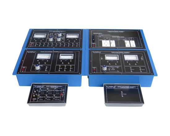
BASIC ELECTRONIC TRAINER (Digital Gates)
Code:EET0476a

It has been designed specifically to study the principle of and NAND,NOT, OR, NOR,&EXORgate. The training board offers a new method of training student in the basic theory of digital circuit and make them familiar with basic experiment in digital circuit.

Practical experience on this board carries great educative value for Science and Engineering Students.

Object:

  • Study of basic gates & verification of their truth tables (AND, NAND, NOT, OR, NOR & EX-ORGate).

Features:

The board consists of the following built-in parts :
  • +5VDC100mAAdopter
  • NAND Gate
  • NOT Gate
  • OR Gate
  • NOR Gate
  • EX-ORGate
  • Switches for logic selection
  • LED's for visual indication of status.
  • The unit is operative on 230V±10% at 50HzA.C. Mains.

BASIC ELECTRONIC TRAINER-2 (Ohm's Law Characteristics)
Code:EET0476b

Experimental Training Board has been designed specifically for the verification of Ohm's Law&to study the series and parallel combination of Resistance network. This training board is quite useful for imparting the basic knowledge of voltage and current distribution and the effect of series parallel circuit.

Object:

  • Verification of ohm's Law.

Features:

The board consists of the following built-in parts :
  • 0-20 V D.C. at 50mA, continuously variable regulated Power Supply.
  • D.C. Voltmeter, 0-20V
  • D.C. Current meter 0-200mA
  • Adequate No. of other electronic components.
  • Mains ON/OFF switch, Fuse and Jewel light.

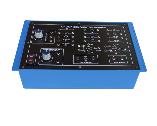
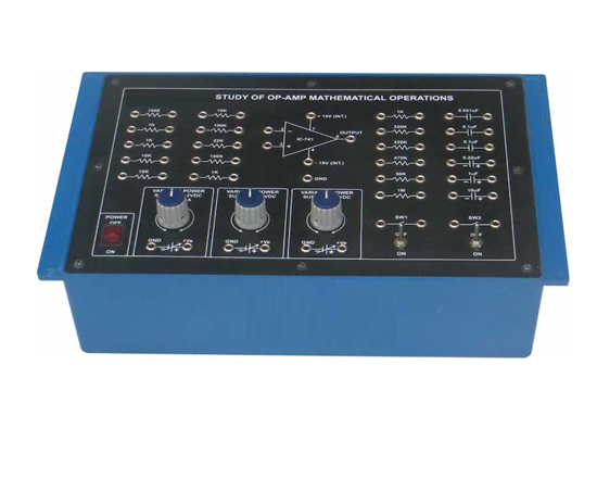
BASIC ELECTRONIC TRAINER (Operational Amplifier)
Code:EET0476c

It has been designed specifically for the study of OP-AMPIC.

List of Experiments

  • Inverting Amplifier
  • Non-invertingAmplifier
  • Voltage Follower (unity Gain Buffer Amplifier)
  • Inverting Summing Amplifier
  • Non-inverting Summing Amplifier
  • Subtractor & Differential Amplifier
  • Division By A Constant
  • Square Wave Generator
  • Off-setAdjustment In Op-amp Circuits
    - For Inverting Amplifier
    - For Non-invertingAmplifier
    - For Voltage Follower
  • Measurement Of Input Offset Voltage (vio )

Features:

  • ± 15DCat100mAIC Regulated power supply
  • Two 0-5V at20mAcontinuously variable power supply
  • One Op-Amp IC-741
  • DC Voltmeter 0-5V
  • DC Voltmeter 0-20V
  • Potentiometer 10K
  • 10 resistance and 1 Capacitor
  • Manse ON/OFF switch fuse Neon Indicator

Other Apparatus Required:

  • 20MHZCathode Ray Oscilloscope
  • Sine Square Wave Oscillator
  • Digital Multimeter

BASIC ELECTRONIC TRAINER (Zener Diode Characteristics)
Code:EET0476d

Experimental Training Board has been designed specifically for plotting the forward and reverse bias characteristics of a Germanium semiconductor Diode, and a Zener Diode. The board is absolutely self contained and requires no other apparatus.

Object

  • To Study And Plot The Forward & Reverse Bias (breakdown) Characteristics of a Zener Diode.

BASIC ELECTRONIC TRAINER (PN Junction Diode Characteristics)
Code:EET0476e

Experimental Training Board has been designed specifically for plotting the forward and reverse bias characteristics of a Germanium semiconductor Diode, and a Zener Diode.

Object

  • To study and plot the forward & reverse bias characteristics of a Germanium semiconductor Diode.

Features:

The board consists of the following built-in parts :
  • 0-10V DC at 100mA, continuously variable regulated Power Supply with low ripple & hum and integral current limiting resistor.
  • DC Voltmeter, Duel range of 1/10V
  • DC Current meter duel range 50uA/10mA
  • A Germanium semiconductor Diode mounted behind the panel.
  • A Zener Diode mounted behind the panel.
  • Adequate no. of other electronic components.
  • Mains ON/OFF switch, Fuse and Jewel light.
  • The unit is operative on 230V±10% at 50HzA.C. Mains.

BASIC ELECTRONIC TRAINER (Domestic Ac Mains Supply Trainer)
Code:EET0476f

It is used to understand the wiring of Domestic AC mains supply. On the panel complete house wiring (after energy meter) is shown but after distribution board wiring is provided. To understand the room wiring of room 1 & room 2 are shown with dotted line on the panel. A three pin socket (5Amp) & a switch in Room 1 and two pin socket & a switch in Room 2 are provided on the panel

Power and Differential Amplifier Trainer

Code:EET0481

BJT Amplifiers and Emitter Follower Trainer

Code:EET0486

BJT Amplifiers and Emitter follower Trainer is a unique product designed to explain the role of BJT's as single-stage/multistage RC-coupled amplifiers and as common collector emitter followers.

One of the common method for coupling two stages of an amplifier is RC-coupling. RC-coupled amplifiers have the advantage of wide frequency response and relatively small cost and size. Darlington transistors are circuits that combine two bipolar transistors in a single device such that high current gain (b) is obtained and lesser space is required than that used by two discrete transistors.

Is useful for students in plotting the frequency vs. Gain response of BJTs and in the measurement of parameters such as Bandwidth, Input Impedance etc.

Scope of Learning

  • Study of the working principle of Differential Amplifier/
  • Study of the working principle of class B push-pull Amplifier

Features:

  • Easy illustration of multistage amplifier and emitter follower
  • In-built sine wave generator with variable frequency and amplitude
  • In- built DC power supply

Technical Specifications:

  • DC power supply : +12 V, +5 V
  • Fuse : 500 mA, slow blow
  • Sine wave generator
  • Frequency : 10 Hz - 100 KHz ±10%
  • Amplitude : 0 to 5 Vpp
  • Mains supply : 230 V ±10%, 50
Educational Equipments
Biology Lab Microscopes Physics Lab Chemistry Lab
Lab Glassware Chinaware & Porcelain ware Lab Platinum-ware Lab Plasticware Stands, Racks, Clamps Wooden Racks and Stands Electro-Chemistry Power Supplies Electrical Spares & Supplies Molecular Models Organic Chemistry Set Laboratory Balances
/ Lab Measuring Instruments
Measurement Aids Spatula Lab Rubber Tubing Chemistry Lab Consumables Lab Brushes Hand Tools and Others Gas Tap & Fittings Lab Testing Papers Chemistry Lab Models Chemistry Charts Lab Safety Supplies Thermometers Laboratory Chemicals
Lab Microscopes & Slides Laboratory Glassware Lab Plasticware Mathematics Lab School/College Science Kits Geography & Geology Teaching Equipments Educational Charts Whiteboard & Boards
Lab Measuring Instruments Electronics Lab Engineering Lab Testing Lab (Engineering) Astronomy Lab Equipments Civil Engineering Equipments Civil Engineering Models Scientific Lab Instruments Blood Bank Equipments Educational Charts