Educational Equipments Manufacturer, Exporters & Suppliers - School Educational Equipments Manufacturers & Exporters of Educational Equipments for Lab. Science Lab Products, Teaching Aids, Classroom Instruments, Educational Laboratory
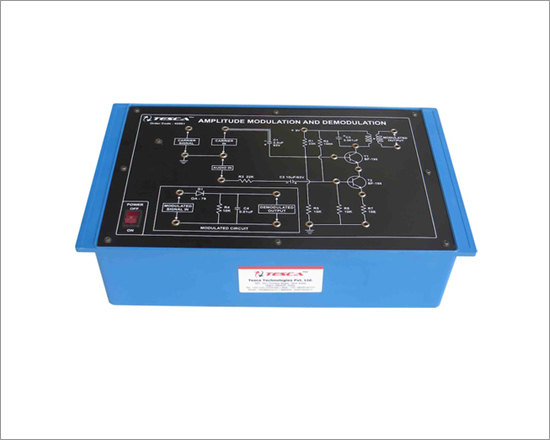
Amplitude Modulation and Demodulation
Code:EET0781
Experimental Training Board has been designed specifically for the study of Amplitude Modulation and Demodulation. This training board is based on latest solid state circuits for generating modulating signal, Amplitude Modulation and Demodulation.
Practical experience on this board carries great educative value for Science and Engineering Students.
Object:
- To study the process of Amplitude Modulation & Demodulation
Experiments:
- To observe the carrier waveforms on C.R.O
- To modulate carrier with audio signal and to observe waveforms on C.R.O
- To measure percentage modulation of the amplitude modulated waveform
- To demodulate amplitude modulated waveform and observe on C.R.O
Features:
The board consists of the following built-in parts :
- +9V D.C. At 100mA, IC Regulated Power Supply internally connected
- Carrier generator circuit which generates carrier wave
- Modulating circuit based on two transistors
- Demodulating circuit
- Adequate no. of other electronic components.
- Mains ON/OFF switch, Fuse and Jewel light.
- The unit is operative on 230V ±10% at 50Hz A.C. Mains.
- Adequate no. of patch cords stackable from rear both ends 4mm spring loaded plug length ½ metre.
- Good Quality, reliable terminal/sockets are provided at appropriate places on panel for connections/ observation of waveforms.
- Strongly supported by detailed Operating Instructions, giving details of Object, Theory, Design procedures, Report Suggestions and Book References.
- Weight: 3 Kg. (Approx.)
- Dimension: W 340 x H 110 x D 210
Other Apparatus Required:
- Decade Audio Frequency Generator
- Cathode Ray Oscilloscope 20MHz
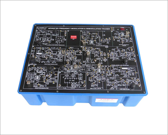
Frequency Modulation & Demodulation

Code:EET0786
Experimental Training Board has been designed specifically for the study of Frequency Modulation and Demodulation
Practical experience on these boards carries great educative value for Science and Engineering Students.
Object:
- To observe the effect of D.C. voltage on frequency of carrier waveform
- To frequency modulate the carrier with Audio signal, observe F.M. waveform on C.R.O., and measure its modulation index
- To demodulate the F.M. singal and observe the output on C.R.O.
- To plot the characteristics curve of the slope detector demodulating circuit
Features:
The board consists of the following built-in parts :
- ± 12V D.C. at 100 mA, IC Regulated Power Supply
- Carrier generator circuit which generates the carrier signal
- Audio frequency modulating signal
- Variable D.C. is provided to see the frequency deviation in carrier frequency
- Frequency Modulation circuit with buffer stage at the output
- Demodulating circuit
- Adequate no. of other electronic components
- Mains ON/OFF switch, Fuse and Jewel light.
- The unit is operative on 230V ±10% at 50Hz A.C. Mains.
- Adequate no. of patch cords stackable from rear both ends 4mm spring loaded plug length ½ metre.
- Good Quality, reliable terminal/sockets are provided at appropriate places on panel for connections/ observation of waveforms.
- Strongly supported by detailed Operating Instructions, giving details of Object, Theory, Design procedures, Report Suggestions and Book References.
- Weight : 3 Kg. (Approx.)
- Dimension : W 340 x H 110 x D 210
Other Apparatus Required:
- Decade Audio Frequency Generator Order Code - EET0786a
- Digital Frequency Counter, 6 digit Order Code - EET0786b
- Cathode Ray Oscilloscope 20MHz
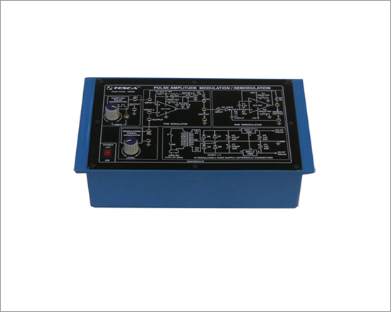
Pulse Amplitude Modulation and Demodulation (PAM)
Code:EET0791
Experimental Training Board has been designed specifically for the study of Pulse Amplitude Modulation & Demodulation. Using this training board one can know the specialized techniques of Pulse Amplitude Modulation and Demodulation.
Practical experience on this board carries great educative value for Science and Engineering Students.
Object:
- To demonstrate sampling of a sine wave audio signal thereby converting it into Pulse Amplitude Modulated Signal (PAM).
- To demonstrate demodulation of PAM signal thereby recovering the sine wave audio signal.
- To demonstrate the effect of sampling-rate on the distortion in recovered ine wave audio signal.
Features:
The board consists of the following built-in parts :
- ±9V D.C. at 100mA, IC regulated Power Supply internally connected
- Variable frequency sampling pulse generator
- Sine wave audio frequency modulating signal generator
- PAM Modulator circuit based on an operational amplifier
- PAM Demodulator circuit based on a point contact diode and an operational amplifier
- Adequate no. of other electronic components.
- Mains ON/OFF switch, Fuse and Jewel light.
- The unit is operative on 230V ±10% at 50Hz A.C. Mains.
- Adequate no. of patch cords stackable from rear both ends 4mm spring loaded plug length ½ metre.
- Good Quality, reliable terminal/sockets are provided at appropriate places on panel for connections/ observation of waveforms.
- Strongly supported by detailed Operating Instructions, giving details of Object, Theory, Design procedures, Report Suggestions and Book References.
- Weight : 3 Kg. (Approx.)
- Dimension : W 340 x H 110 x D 210
Other Apparatus Required:
- Cathode Ray Oscilloscope 20MHz
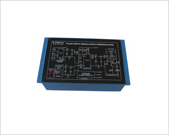
Pulse Width Modulation & Demodulation (PWM)
Code:EET0796
Experimental Training Board has been designed to study on the modern techniques of Pulse Width Modulation / Demodulation. Using this training board one can know the specialized techniques of Pulse Width Modulation and Demodulation
Practical experience on this board carries great educative value for Science and Engineering Students.
Object:
- To modulate a pulse carrier with sinusoidal signal to obtain a Pulse Width Modulated signal
- To demodulate the Pulse Width Modulated signal to obtain the modulating signal
Features:
The board consists of the following built-in parts :
- ± 6V D.C. at 100mA, IC regulated Power Supply internally connected
- Pulse Train (Carrier) Generator based on timer IC
- 50 Hz A.C. sinusoidal modulating signal obtained from stepped down transformer
- Pulse Width Modulator based on timer
- Pulse Width Demodulator based on operational amplifier
- Adequate no. of other electronic components.
- Mains ON/OFF switch, Fuse and Jewel light.
- The unit is operative on 230V ±10% at 50Hz A.C. Mains.
- Adequate no. of patch cords stackable from rear both ends 4mm spring loaded plug length ½ metre.
- Good Quality, reliable terminal/sockets are provided at appropriate places on panel for connections/ observation of waveforms.
- Strongly supported by detailed Operating Instructions, giving details of Object, Theory, Design procedures, Report Suggestions and Book References.
- Weight : 3 Kg. (Approx)
- Dimension : W 340 x H 110 x D 210
Other Apparatus Required:
- Cathode Ray Oscilloscope 20MHz
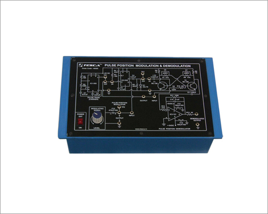
Pulse Position Modulation & Demodulation (PPM)
Code:EET0801
Experimental Training Board has been designed specifically for the study of Pulse Position Modulation and Demodulation. Using this training board one can know the specialized techniques of Pulse Position Modulation and Demodulation.
Practical experience on these boards carries great educative value for Science and Engineering Students.
Object:
- To modulate a pulse train (carrier) with a sinusoidal signal and to obtain a pulse Position Modulated signal
- To demodulate a Pulse Position Modulated signal to recover the modulating signal
Features:
The board consists of the following built-in parts :
- ± 6V D.C. at 100mA, IC regulated Power Supply internally connected
- Pulse Train (Carrier) Generator based on timer IC
- 50 Hz A.C. sinusoidal modulating signal obtained from stepped down transformer
- Pulse Position Modulating circuit based on IC
- Demodulating circuitry based on an IC and transistors
- Adequate no. of other electronic components.
- Mains ON/OFF switch, Fuse and Jewel light.
- The unit is operative on 230V ±10% at 50Hz A.C. Mains.
- Adequate no. of patch cords stackable from rear both ends 4mm spring loaded plug length ½ metre.
- Good Quality, reliable terminal/sockets are provided at appropriate places on panel for connections/ observation of waveforms.
- Strongly supported by detailed Operating Instructions, giving details of Object, Theory, Design procedures, Report Suggestions and Book References.
- Weight : 3 Kg. (Approx.)
- Dimension : W 340 x H 110 x D 210
Other Apparatus Required:
- Cathode Ray Oscilloscope 20MHz
Frequency Shift Keying Modulation And Demodulation
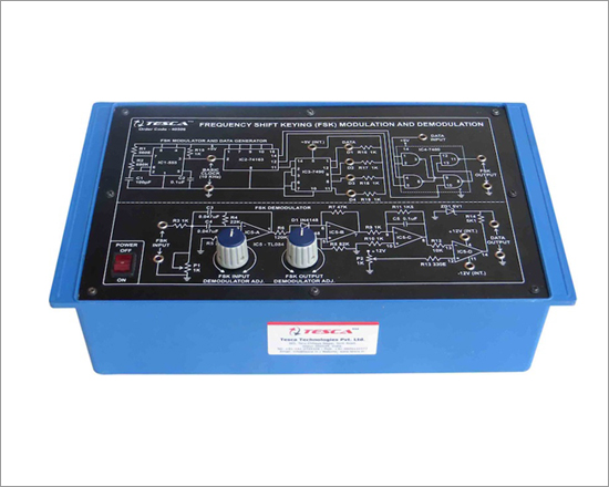
Code:EET0806
Experimental Training Board has been designed specifically for the study of frequency shift keying modulation and Demodulation. The board is absolutely self contained and requires only CRO.
Practical experience on these boards carries great educative value for Science and Engineering Students.
Object:
- To study the generation of the Frequency Shift Keyed output and also to demodulate the FSK output.
Features:
The board consists of the following built-in parts :
- ± 12V D.C. at 20mA IC regulated power supply internally connected
- 5V D.C. at 100mA IC regulated power supply internally connected
- Quad Op-amp IC
- Decade counter IC
- Timer IC
- 4-Bit Binary counter IC
- Quad 2-input Nand gate IC
- Two potentiometers for varying the FSK input and demodulator adjust
- Adequate no.of other electronic components
- Mains ON/OFF switch, Fuse and Jewel light.
- The unit is operative on 230V ±10% at 50Hz A.C. Mains.
- Adequate no. of patch cords stackable from rear both ends 4mm spring loaded plug length ½ metre.
- Good Quality, reliable terminal/sockets are provided at appropriate places on panel for connections/ observation of waveforms.
- Strongly supported by detailed Operating Instructions, giving details of Object, Theory, Design procedures, Report Suggestions and Book References.
- Weight : 3 Kg. (Approx.)
- Dimension : W 340 x H 110 x D 210
Other Apparatus Required:
- Cathode Ray Oscilloscope 20MHz
Phase Shift Keying Modulation and Demodulation
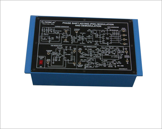
Code:EET0811
Experimental Training Board has been designed specifically for the study the Phase shift keying modulation and Demodulation. The board is absolutely self contained and requires only CRO.
Practical experience on these boards carries great educative value for Science and Engineering Students.
Object:
- To study the generation of the Phase Shift Keyed output and also to demodulate the PSK output.
Features:
The board consists of the following built-in parts :
- ± 5V D.C. at 100mA IC regulated power supply internally connected
- Op-Amp IC.
- Decade counter IC.
- Quad Op-Amp. IC
- Multiplexer IC.
- Quad, 2-input EX-OR gate IC
- Mains ON/OFF switch, Fuse and Jewel light.
- The unit is operative on 230V ±10% at 50Hz A.C. Mains.
- Adequate no. of patch cords stackable from rear both ends 4mm spring loaded plug length ½ metre.
- Good Quality, reliable terminal/sockets are provided at appropriate places on panel for connections/ observation of waveforms.
- Strongly supported by detailed Operating Instructions, giving details of Object, Theory, Design procedures, Report Suggestions and Book References.
- Weight : 3 Kg. (Approx.)
- Dimension : W 340 x H 110 x D 210
Other Apparatus Required:
- Cathode Ray Oscilloscope 20MHz
Amplitude Shift Key Modulation And Demodulation
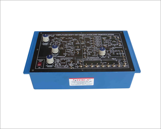
Code:EET0816
Experimental Training Board has been designed specifically for the study of Amplitude shift key modulation and Demodulation. The board is absolutely self contained and requires only CRO.
Practical experience on these boards carries great educative value for Science and Engineering Students.
Object:
- To study the generation of the Amplitude Shift Key output and also to demodulate the ASK output.
Features:
The board consists of the following built-in parts :
- ± 12V D.C. at 50mA, IC regulated power supply internally connected.
- ± 5V D.C. at 50mA, IC regulated power supply internally connected.
- Clock Generator 200Hz to 15KHz.
- 8 Bit Word Generator.
- Logic Selection switches for high / low (9Nos).
- Binary Counter (Divided by 16 counter).
- Carrier Signal Generator 4 to 10KHz.
- Amplitude Shift Key (ASK) Modulator.
- Amplitude Shift Key (ASK) Demodulator.
- Mains ON/OFF switch, Fuse and Jewel light.
- The unit is operative on 230V ±10% at 50Hz A.C. Mains
- Adequate no. of patch cords stackable from rear both ends 4mm spring loaded plug length ½ metre.
- Good Quality, reliable terminal/sockets are provided at appropriate places on panel for connections/ observation of waveforms.
- Strongly supported by detailed Operating Instructions, giving details of Object, Theory, Design procedures, Report Suggestions and Book References.
Other Apparatus Required:
- Cathode Ray Oscilloscope 20MHz
Delta Modulation and Demodulation
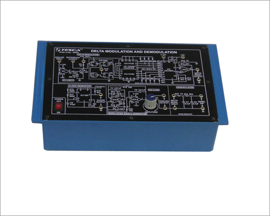
Code:EET0821
Experimental Training Board has been designed specifically for study of delta modulation and demodulation The board is absolutely self contained and requires only CRO.
Practical experience on these boards carries great educative value for Science and Engineering Students.
Object:
- To study delta modulation and demodulation.
Features:
The board consists of the following built-in parts :
- ±12V D.C. at 100mA IC regulated power supply internally connected.
- Quad Op-Amp IC.
- Two Up/Down counter IC.
- Digital to Analog convertor DAC IC.
- Quad two input NAND gate IC.
- Timer IC.
- Cooperator IC.
- 5V D.C. at 100mA IC regulated power supply internally connected.
- Potentiometer for varying amplitude of modulating signal.
- Mains ON/OFF switch, fuse and Neon Indicator are provided.
- The unit is operative on 230V ±10% at 50Hz A.C. Mains.
- Adequate no. of patch cords stackable from rear both ends 4mm spring loaded plug length ½ metre.
- Good Quality, reliable terminal/sockets are provided at appropriate places on panel for connections/ observation of waveforms.
- Strongly supported by detailed Operating Instructions, giving details of Object, Theory, Design procedures, Report Suggestions and Book References.
- Weight : 3 Kg. (Approx.)
- Dimension : W 340 x H 110 x D 210
Other Apparatus Required:
- Cathode Ray Oscilloscope 20MHz
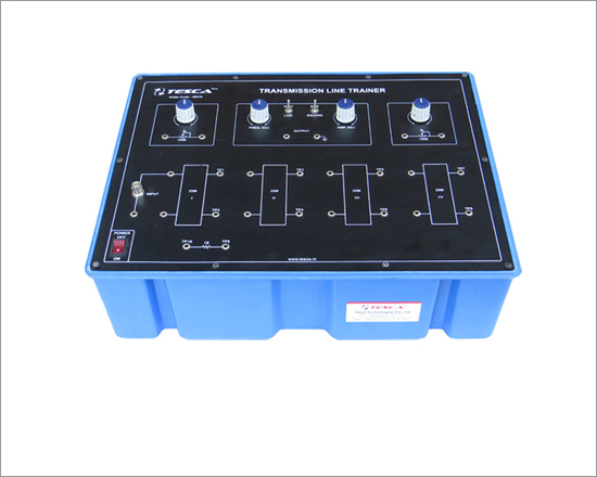
Transmission Line Trainer
Code:EET0826
Experimental Training Board has been designed specifically to study the various parameters in Transmission Line. Practical experience on this board carries great educative value for Science and Engineering Students.
Object:
- Measuring the characteristics of a line
- Measuring the attenuation of a line
- Measuring the Input Impedance of the line
- Phase displacement between the current & voltage at input of line
- Frequency characteristic of the line
- Study of Stationary Waves
- Signal phase shift along the line
- Fault localization within the line
- Line under pulsed condition.
Features:
- 4 Nos. Coaxial Cables 25 meters each, total Transmission line 100 metres.
- Two potentiometers for impedance matching.
- Sine/Square wave Signal Generator having frequency 40KHz to 4MHz, in two bands 40KHz to 400KHz & 400KHz to 4MHz.
- A SPDT switch to select either sine or square wave.
- A SPDT switch to select frequency either high (400KHz to 4MHz) or low (40KHz to 400KHz).
- A potentiometer to vary frequency high (400KHz to 4MHz) or low (40KHz to 400KHz).
- A potentiometer to vary amplitude.
- BNC connector to connect input.
- Adequate no. of other electronic components
- Mains ON/OFF switch, Fuse and Jewel light.
- The unit is operative on 230V ±10% at 50Hz A.C. Mains.
- Adequate no. of patch cords stackable from rear both ends 4mm spring loaded plug length ½ metre.
- Good Quality, reliable terminal/sockets are provided at appropriate places on panel for connections/ observation of waveforms.
- Strongly supported by detailed Operating Instructions, giving details of Object, Theory, Design procedures, Report Suggestions and Book References.
- Weight : 5 Kg. (Approx.)
- Dimension : W 320 x H 190 x D 235
Other Apparatus Required:
- Cathode Ray Oscilloscope 20MHz.
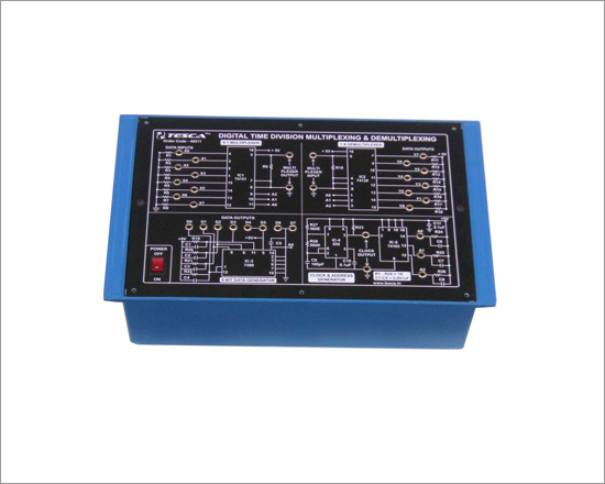
Digital Time Division Multiplexing & Demultiplexing
Code:EET0831
Experimental Training Board has been designed specifically to study Digital time division multiplexing & demultiplexing. 8 channel Digital Multiplexer and Demultiplexer are provided on the Trainer. A rolling Address Generator scans the 8 channels sequentially. Data Generator with 8 different outputs act as signal sources for the 8 channels. Practical experience on this board carries great educative value for Science and Engineering Students.
Object:
- To study Digital Time Division Multiplexing & Demultiplexing.
Features:
The board consists of the following built-in parts :
- ± 5V D.C. at 100mA IC regulated power supply internally connected.
- 8 : 1 Multiplexer.
- 1 : 8 Demultiplexer.
- 8 bit Data Generator.
- Clock & Address Generator.
- Mains ON/OFF switch, Fuse and Jewel light.
- The unit is operative on 230V ±10% at 50Hz A.C. Mains.
- Adequate no. of patch cords stackable from rear both ends 4mm spring loaded plug length ½ metre.
- Good Quality, reliable terminal/sockets are provided at appropriate places on panel for connections/ observation of waveforms.
- Strongly supported by detailed Operating Instructions, giving details of Object, Theory, Design procedures, Report Suggestions and Book References.
- Weight : 3 Kg. (Approx.)
- Dimension : W 340 x H 110 x D 210
Other Apparatus Required:
- Dual Trace Cathode Ray Oscilloscope 20MHz.
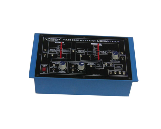
Pulse Code Modulation & Demodulation Trainer
Code:EET0836
Experimental Training Board has been designed specifically to study Pulse Code Modulation & Demodulation. In the basic PCM Modulator the base band analog signal is covered into 8 bit digital format using an ADC. The sampling rate is set at 2.5 KHz. The 8 bit parallel data from ADC is converted into serial bit stream at 33 kbps.The PCM Demodulator receives the serial data, converts it into 8 bit parallel format. The Analog to digital converter transforms the 8 bit parallel data into analog level. Thus the output of DAC is a stepped approximation of input signal. A low pass filter is used to recover the analog signal.Practical experience on this board carries great educative value for Science and Engineering Students.
Object:
- To study Pulse Code Modulation & Demodulation.
Features:
The board consists of the following built-in parts :
- 5V D.C. at 100mA IC regulated power supply internally connected.
- ± 15V D.C. at 100mA IC regulated power supply internally connected.
- + 5V D.C. to -9V Variable D.C. output.
- Built in TTL Clock Generator 33 KHz.
- Modulating Signal Generator 15Hz to 300Hz.
- PCM Encoder.
- PCM Decoder.
- Data display with LED's
- Adequate no. of other electronic components
- Mains ON/OFF switch, Fuse and Jewel light.
- The unit is operative on 230V ±10% at 50Hz A.C. Mains.
- Adequate no. of patch cords stackable from rear both ends 4mm spring loaded plug length ½ metre.
- Good Quality, reliable terminal/sockets are provided at appropriate places on panel for connections/ observation of waveforms.
- Strongly supported by detailed Operating Instructions, giving details of Object, Theory, Design procedures, Report Suggestions and Book References.
- Weight : 3 Kg. (Approx.)
- Dimension : W 340 x H 110 x D 210
Other Apparatus Required:
- Cathode Ray Oscilloscope 20MHz.
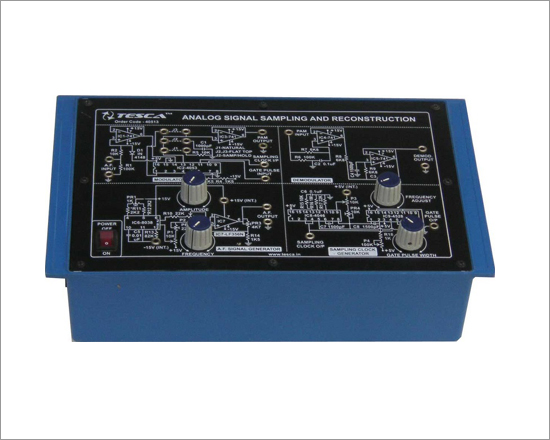
Analog Signal Sampling and Reconstruction
Code:EET0841
Experimental Training Board has been designed specifically to study of Sampling Theorem using Pulse Amplitude Modulation and Demodulation. The training board is complete in all respect except C.R.O. Practical experience on this set up carries great educative value for Science and Engineering Students.
Object:
- To generate PAM signal by modulating with audio signal by natural sampling.
- To generate PAM signal by modulating with audio signal by Flat-Top sampling.
- To generate PAM signal by modulating with audio signal by Sample / Hold circuit.
- To demodulate using Low Pass Filter to reconstruct input(sine wave).
Features:
The board consists of the following built-in parts :
- ±15V D.C. at 100mA, IC Regulated Power Supply.
- +5V D.C. at 100mA, IC Regulated Power Supply.
- A.F. signal generator for modulating signal.
- Sampling clock generator to provide sampling clock and gate pulse.
- Modulator circuit for Flat-top natural and S/H circuit.
- Demodulator circuit to reconstruct input (sinewave).
- Mains ON/OFF switch, Fuse and Jewel light.
- Adequate no. of patch cords stackable from rear both ends 4mm spring loaded plug length ½ metre.
- Good Quality, reliable terminal/sockets are provided at appropriate places on panel for connections/ observation of waveforms.
- Strongly supported by detailed Operating Instructions, giving details of Object, Theory, Design procedures, Report Suggestions and Book References.
- Weight : 3 Kg. (Approx.)
- Dimension : W 340 x H 110 x D 210
Other Apparatus Required:
- Dual Scope Cathode Ray Oscilloscope 20MHz.
Differential Pulse Code Modulation and Demodulation Trainer
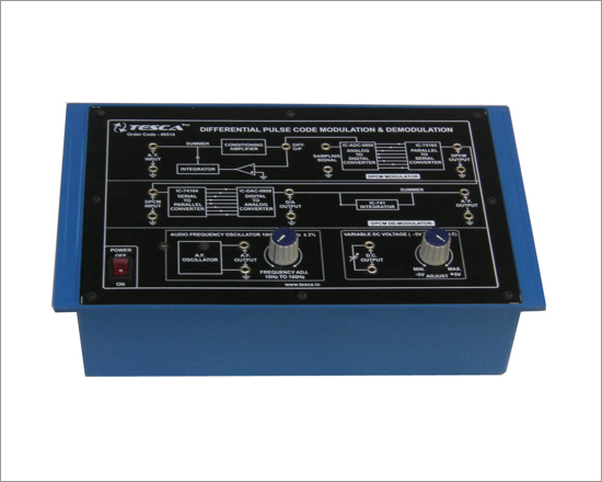
Code:EET0846
Experimental Training Board has been designed specifically to study Differential Pulse Code Modulation & Demodulation. In the basic DPCM Modulator the base band analog signal is covered into 8 bit digital format using an ADC. The sampling rate is set at 2.5 Khz.The DPCM Demodulator receives the serial data, converts it into 8 bit parallel format. The Digital to Analog converter transforms the 8 bit parallel data into analog level. Thus the output of DAC is a stepped approximation of input signal. A low pass filter is used to recover the analog signal.
Practical experience on these boards carries great educative value for Science and Engineering Students.
Object:
- To study Differential Pulse Code Modulation & Demodulation.
Features:
The board consists of the following built-in parts :
- 5V D.C. at 100mA IC regulated power supply internally connected.
- ± 12V D.C. at 100mA IC regulated power supply internally connected.
- - 5V D.C. to + 5V D.C. Variable D.C. output.
- Audio Frequency Oscillator 10Hz to 100Hz for modulation.
- DPCM Modulator (DPCM ENCODER).
- DPCM Demodulator (DPCM DECODER).
- Adequate no. of other electronic components.
- Mains ON/OFF switch, Fuse and Jewel light.
- The unit is operative on 230V ±10% at 50Hz A.C. Mains.
- Adequate no. of patch cords stackable from rear both ends 4mm spring loaded plug length ½ metre.
- Good Quality, reliable terminal/sockets are provided at appropriate places on panel for connections/ observation of waveforms.
- Strongly supported by detailed Operating Instructions, giving details of Object, Theory, Design procedures, Report Suggestions and Book References.
- Weight : 3 Kg. (Approx.)
- Dimension : W 340 x H 110 x D 210
Other Apparatus Required:
- Dual Trace Cathode Ray Oscilloscope 20MHz.
Differential Phase Shift Keying Modulation and Demodulation
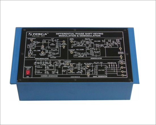
Code:EET0851
Experimental Training Board has been designed specifically to study Differential Phase Shift Keying (DPSK) Modulation and Demodulation. Practical experience on this board carries great educative value for Science and Engineering Students. The unit is absolutely self contained except CRO.
Object:
- To study Differential Phase Shift Keying Modulation and Demodulation
Features:
The board consists of the following built-in parts :
- ± 5V D.C. at 100mA IC regulated Power Supply internally connected.
- IC-1 for generating DPSK (Differential Phase Shift Keying) signal.
- IC-5 for generating Carrier signals.
- IC-2A for generating Bit Clock.
- IC-6 for generating different Datas.
- IC-2 B & C, IC-3 C & D, IC-4 D-FF2 and Transistor 2, 3 & 4 are used as Demodulator.
- Adequate no. of Electronic Components.
- Mains ON/OFF switch, fuse and Neon Indicator are provided.
- The unit is operative on 230V ±10% at 50Hz A.C. Mains.
- Adequate no. of patch cords stackable from rear both ends 4mm spring loaded plug length ½ metre.
- Good Quality, reliable terminal/sockets are provided at appropriate places on panel for connections/ observation of waveforms.
- Strongly supported by detailed Operating Instructions, giving details of Object, Theory, Design procedures, Report Suggestions and Book References.
- Weight : 3 Kg. (Approx.)
- Dimension : W 340 x H 110 x D 210
Other Apparatus Required:
- Dual Trace Cathode Ray Oscilloscope 20MHz
DSB / SSB-SC Amplitude Modulation & Demodulation Trainer
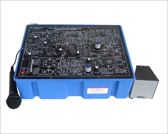
Code:EET0856
DSB/SSB-SC Amplitude Modulation & Demodulation Trainer has been designed with a view to provide practical and experimental knowledge of Amplitude Modulation / Demodulation technique as practically implemented in Analog Communication system on a SINGLE P.C.B. of size 300x400mm.
Object:
- 01. Amplitude Modulation & Demodulation.
1.1 Generate AM signal by modulation with audio signal generator
1.2 Measure modulation index of A.M. signal
1.3 Demodulate AM signal using diode detector(envelope detector)
1.4 Generate voice signal AM modulation and demodulation using Mic.
1.5 Observe the effect of DC signal input on AM output
1.6 Demodulate AM signal by square law detection
- 02. DSB-SC Amplitude Modulation & Demodulation.
2.1 Generate DSB-SC AM signal
2.2 Demodulate DSB-SC signal using product detector
- 03. SSB-SC Amplitude Modulation & Demodulation
3.1 Generate SSB-SC AM signal
3.2 Demodulate SSB-SC signal using product detector
Features:
The board consists of the following built-in parts :
- IC REGULATED POWER SUPPLY : ± 15 DC and +5V DC at 100mA.
- AF Modulation signal generator : Sine wave
Frequency Range : 300 Hz to 3.4 KHz
Amplitude : 0 to 5 Vpp.
- RF carrier signal oscillator.
Frequency Range : 100 KHz to 1 MHz.
Amplitude : 0 to 10 Vpp.
- Local Oscillator : 400 KHz to 500 KHz.
- Band Pass Filter : 452 KHz to 458 KHz.
- DC Source Variable power supply to
- see the effect of DC on the output waveform : - 5 to + 5 VDC
- Output Audio amplifier with Volume Control.
- Input Audio amplifier for modulating external signal from Mike or Tape recorder.
- Duble Balanced Amplitude modulator
- Diode detector.
- Product detector
- Low pass filter.
- Power supply requirement 230V AC, 50 Hz.
- Mains ON/OFF switch, fuse and jewel light.
- Dynamic Microphone with 4mm Jack Pin.
- Loud Speaker with baffle fitted in a box with two metre wire and 2mm Banana pins for connections.
- Good Quality, reliable terminal/sockets are provided at appropriate places on panel for connections/ observation of waveforms.
- Strongly supported by detailed Operating Instructions, giving details of Object, Theory, Design Procedures, Report Suggestions and Book References.
- Weight : 6 Kg. (Approx.)
- Dimension : W 412 x H 150 x D 310
Other Apparatus Required:
- Cathode Ray Oscilloscope 20MHz.
DSB / SSB AM Transmitter Trainer
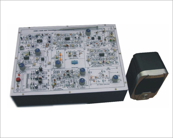
Code:EET0861
This trainer has been designed with a view to provide practical and experimental knowledge of DSB / SSB AM Transmitter technique as practically implemented in Analog Communication system on a signal P.C.B. of size 300x400mm.
Object:
- Study of carrier frequency generation.
- Study of DSB / SSB AM Generation & Transmission.
- Study of Transmitter tuned circuits.
Features:
The board consists of the following built-in parts :
- AF Modulating signal generator : Sine wave
- Frequency Range : 300 Hz to 3.4 KHz
- Amplitude : 0 to 5 Vpp.
- RF carrier signal oscillator
- Amplitude : 0 to 10 Vpp.
- Frequency Range : 100 KHz to 1 Mhz.
- Modulators (Two Nos) : Double Balanced Amplitude modulator
- Ceramic Band Pass Filter : 452 KHz to 458 KHz.
- Band Pass Filter : 1 No.
- Switch faults : 8 Nos.
- POWER SUPPLY : ± 12DC and +5V DC IC Regulated power supply.
- Test points : 27 Nos.
- BFO Oscillator : 455 KHz.
- Input Audio amplifier with Volume Control for modulating external signal from Mike or Tape recorder.
- Output Amplifier Transmitter : ( Gain adjustable) DSB (1MHz), SSB (1.445 MHz) connected to Antenna/cable.
- Mains ON/OFF switch, fuse and jewel light.
- Power supply requirement 230V AC, 50 Hz.
- Dynamic Microphone with 4mm Jack Pin.
- Good Quality, reliable terminal/sockets are provided at appropriate places on panel for connections/ observation of waveforms.
- Strongly supported by detailed Operating Instructions, giving details of Object, Theory, Design Procedures, Report Suggestions and Book References
- Weight : 6 Kg. (Approx.)
- Dimension : W 412 x H 150 x D 310
Other Apparatus Required:
- Cathode Ray Oscilloscope 20MHz.
DSB / SSB AM Receiver Trainer

Code:EET0866
DSB / SSB AM Receiver trainer this trainer has been designed with a view to provide practical and experimental knowledge of DSB / SSB AM.Receiver technique as practically implemented in Analog Communication system on a signal P.C.B. of size 300x400mm
Object:
- 01. Study of DSB & SSB AM reception & deletion by diode / product detectors.
- 02. Study of AGC.
- 03. Study of receiver tuned circuits.
- 04. Study of Sensitivity, Selectivity & Fidelity of Receiver.
Experiments
- 01. Study of double sideband AM reception using envelope detector via cable.
- 02. Study of double sideband AM reception using envelope detector via Antenna.
- 03. Study of sensitivity, selectivity, of a radio receiver.
- 04. Study of single sideband AM reception using product detector.
- 05. Study of Image frequencies.
- 06. Voice transmission with DSB AM transmission / reception.
Features:
The board consists of the following built-in parts :
- POWER SUPPLY : ± 12DC and +5V DC IC Regulated power supply.
- 02. Detectors/Demodulator :
1. Diode Detector (For DSB)
2. Product Detector (For SSB)
- 03. Frequency Range : 980KHz to 1650 KHz.
- 04. Intermediate frequency : 455 KHz.
- 05. Input Circuits :
1. RF Amplifier
2. Mixer
3. 1st Amplifier
4. 2nd Amplifier
5. Local oscillator
6. Envelope Detector (AGC)
7. Switch Fault
8. Product Detector
9. IC Regulated Power Supply
10. Beat frequency oscillator / 455 KHz Crystal oscillator
11. Output Audio Amplifier
- 06. Receiving media : Telescopic Antenna / cable.
- 07. Tuning : with variable capacitor.
- 08. Switched faults : 8Nos.
- 09. Test points : 50.
- 10. Power supply requirement : 230V AC, 50 Hz.
- 11. Mains ON/OFF switch, fuse and LED.
- 12. Audio Output amplifier with Volume Control.
- 13. Loud Speaker with baffle fitted in a box with two metre wire and 2mm Banana pins for connections.
- Adequate no. of patch cords stackable from rear both ends 4mm spring loaded plug length ½ metre.
- Good Quality, reliable terminal/sockets are provided at appropriate places on panel for connections/ observation of waveforms.
- Strongly supported by detailed Operating Instructions, giving details of Object, Theory, Design procedures, Report Suggestions and Book References.
- Weight : 6 Kg. (Approx.)
- Dimension : W 412 x H 150 x D 310
Other Apparatus Required:
- Cathode Ray Oscilloscope 20MHz.
Note: Specifications are subject to change. Order Code can be different from Manufacturer's Model No.
FM Transmitter & Receiver Trainer
Code:EET0871
FM Transmitter and Receiver Trainer has been designed with a view to provide practical and experimental knowledge of Frequency Modulation / Demodulation technique as practically implemented in Analog Communication system on a SINGLE P.C.B. of size 300x400mm.
Object:
- 01. Frequency Modulation via varactor / reactance Modulation.
02. Frequency Demodulation via Detuned Resonant / Ratio / Qudrature / Foster - Seeley / Phase locked loop detector.
03. Separate VCO circuit to demonstrate FM waveform.
Features:
The board consists of the following built-in parts :
- POWER SUPPLY : ± 12DC IC Regulated power supply.
- 02. FM Modulating signal generator : Sine wave
Frequency Range : 300 Hz to 3.4 Khz
Amplitude Range : 0 to 5 Vpp.
- 03. Modulator Type :
Varactor modulator (With carrier frequency adjustment)
Reactance Modulator (With carrier frequency adjustment)
- 04. Demodulator :
Detuned resonant detector.
Quadrature detector
Foster - Seeley Detector
Ratio Detector
Phase locked loop Detector
- 05. Mixer/Amplifier :
1 No. (With gain adjustment) Allows FM input signal to be amplitude modulated by a noise input to demodulation.
- 06. Low pass Filter :
3.4 KHz.:Cut of frequency Amplifier (with adjustable gain)
- 07. VCO Circuit :
FM Wave form demonstrate
- 08 Test Point : 78
- 09. Power supply requirement :230VAC, 50 Hz.
- 10. On Board Switched Faults : 8 Nos.
- 11. On Board Amplitude limiter with Amplitude control.
- 12. Input - Output and Test points provided on board.
- 13. A self contained Trainer.
- 14. Effect of noise on the detection of FM signal may be investigated.
- Good Quality, reliable terminal/sockets are provided at appropriate places on panel for connections/ observation of waveforms.
- Strongly supported by detailed Operating Instructions, giving details of Object, Theory, Design procedures, Report Suggestions and Book References.
- Weight : 6 Kg. (Approx.)
- Dimension : W 412 x H 150 x D 310
Other Apparatus Required:
- Cathode Ray Oscilloscope 20MHz.
- Patch Cords
Delta, Adaptive Delta and Delta Sigma Modulation / Demodulation Trainer
Code:EET0876
In digital communication specially operating at low frequencies or speech communications a saving in Bandwidth can be resulted using Delta Modulation and its associated techniques because this requires single encoding of sample. This Trainer covers Delta, Adaptive Delta and Delta sigma Modulation and Demodulation.
Technical Specifications
- Crystal Frequency : 6.400 MHz
- Sampling Clock Frequency : 50, 100, 200 & 400 KHz (Switch selectable)
- On board Generator : Synchronized & Adjustable Amplitude Sine Wave Generator of 1 KHz, 2 KHz, 3 KHz, 4 KHz Separate Variable D.C. level
- Integrator : Four integrator gain settings Normal, X 2, X 4, X 8
- Low Pass Filter : Fourth order Butterworth (Cut Off Frequency 4.8 KHz)
- Test Points : 43
- Interconnections : 2 mm socket
- Power Supply : 220 V ±10%, 50 Hz / 60 Hz on request
- Power Consumption : 4 VA (approx.)
Features:
- Transmitter and Receiver on same board
- Clock generation from crystal
- Switch selectable sampling rates
- Four on-board generators at 4 different frequencies (synchronized)
- Separate adjustable DC level
- Selectable integrator gain setting (by switch or control circuit)
- On board 4th order Butterworth low pass filter
- Unipolar to Bipolar converter on board
Experiments:
- Delta Modulation & Demodulation
- Effect of slope overload and increased integrator gain in Delta Modulation
Adaptive Delta Modulation & Demodulation
- Delta Sigma Modulation & Demodulation
- Amplitude overload in Delta Sigma Modulation


