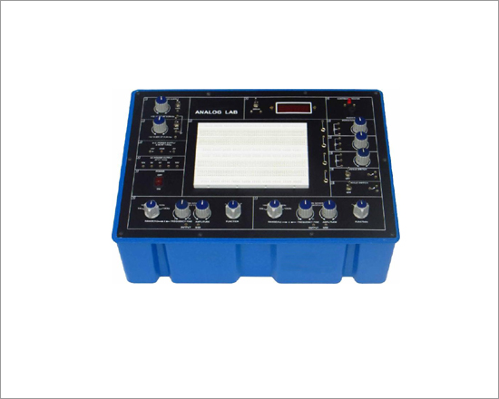
Analog Lab
Code:EET0591
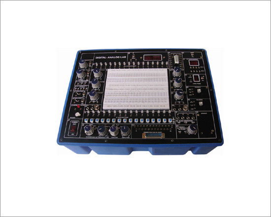
ANALOGLAB is intended for elementary as well as advance training of analog electronics.The trainer covers regular analog circuits by solderless interconnections on breadboard and as well as compatible with all optional modules, through use of 2mm brass terminals and patch cords. Various DC regulated power supplies, Function Generator, DMM, Continuity Tester etc are in-built. The unit housed in attractive enclosure is supplied with mains cord, patch cords, Instruction manual and Component Set.
Experimental Coverage:
- Study of Diodes in DC circuits
- Study of Light Emitting Diodes in DC Circuits
- Study of Half wave rectifier
- Study of Full wave rectifier
- Study of Zener Diode as a voltage regulator
- Study of transistor series voltage regulator
- Study of transistor shunt voltage regulator
- Study of Low pass filter
- Study of High pass filter.
- Study of band pass filter
- Study of CE configuration of NPN transistor
- Study of CB configuration of NPN transistor
- Study of CE amplifier
- Study of Monostable multivibrator using transistor
- Study of Bistable multivibrator using transistor
- Study of Astable multivibrator using transistor
- Study of CB Amplifier (PNP)
- Study of CC Amplifier (PNP)
- Transistor Audio Amplifier
- Two Stage R.C. Coupled Transistor
- Inverting Amplifier
- Non-inverting Amplifier
- Integrating Amplifier for A.C input Signal
- Differentiator Amplifier
- Square Wave Generator
Features:
- Bread Board : Unique solder-less large size, spring loaded breadboard consisting of two Terminal Strips with 1280 tie points and 4 Distribution Strips with 100 tie points each, totaling to 1680 tie points. (Size:112mm x 170mm approx)
- Regulated DC Power Supply : +5V at 1 Amp, -5V at 1Amp, +12V/0 to 20V at 500mA, and -12 V/0 to -20V at 500 mA
- AC Supply : 5-0-5V, 10-0-10V at 100mA. Can be used as 5V,10V,15V,20V and also as center tap
- Function Generator : Sine / Square / Triangular waveforms frequency 1 Hz to 110 KHz in 5 Steps. Variable in between steps. Sine / Square / Triangular waveform output 50mV ~10Vpp variable
- Modulation Generator : Sine / Square / Triangular wave forms frequency 1 Hz to 110 KHz in 5 Steps. Variable in between (100 KHz ) steps. Sine / Square / Triangular waveform output 50mV ~ 10Vpp variable with 100 KHz Modulation
- Digital Meter (3½Digit) : Dual range DC voltmeter 0-20 V / Ammeter 0-200mA
- Continuity Tester : For testing the continuity. Provided with Beeper Sound
- Potentiometers : 3 Potentiometers (1K, 100K and 100K) with terminals
- On Board Switches : 2 Switches Single pole double through
- Power : 230 V ± 10%, 50 Hz
- Components Provided : Resistance ± 5% 1W 100E/1, ½ W 47E/2,100E/1, 220E/1, 390E/1,1K/1,¼W 100E/1, 220E/2, 270E/1, 330E/, 1K/3, 2K2/2, 3K3/1, 4K7/2, 5K1/1, 5K6/1, 10K/2, 12K/1, 15K/2, 47K/2, 68K/1, 100K/4, 180K/2, 220K/1 Capacitor 0.1uF/1, 0.22uF/3, 10uF/25V/3, 22uF/25V/2, 47uF/25V/2, 100uF/25V/1, Diode 1N 4007/4, LED 5mm Red/1, Zener Diode 5V6/400mW/1, Transistor SL 100/1, SK 100/1, BC 107/2, BC 177/2,IC 741/2
- Accessories : Mains cord, Operating and Experimental manual, Red & Black patch cords (2mm with Pin) 10 each, Red & Black patch cord (Pin to Pin) 10 each & Component Set
- Instruction manual : Strongly supported by detailed operating instructions
- * Weight : 5 Kg. (Approx.)
- * Dimension : W 412 x H 150 x D 310
Optional modules:
Apart from above given experimental coverage of 25 experiments on breadboard, customers can purchase these optional modules. These are ready to use modules with wired components & circuit schematic drawn on top compatible to use with Analog Lab.
- EET0591a - Study of Diodes in DC circuits
- EET0591b - Study of Light Emitting Diodes in DC Circuits
- EET0591c - Study of Half wave rectifier
- EET0591d - Study of Full wave rectifier
- EET0591e - Study of Zener Diode as a voltage regulator
- EET0591f - Study of transistor series voltage regulator
- EET0591g - Study of transistor shunt voltage regulator
- EET0591h - Study of Low pass filter
- EET0591i - Study of High pass filter
- EET0591j - Study of band pass filter
- EET0591k - Study of CE configuration of NPN transistor
- EET0591l - Study of CB configuration of NPN transistor
- EET0591m - Study of CE amplifier
- EET0591n - Study of Monostable multivibrator using transistor
- EET0591o - Study of Bistable multivibrator using
- EET0591p- Study of Astable multivibrator using transistor
- EET0591q - Study CB amplifier (PNP)
- EET0591r - Study CC amplifier (PNP)
- EET0591s - Study Zener diode voltage regulator
- EET0591t - Study power supply having two zener diodes in series
- EET0591u - Study dual polarity voltage regulated supply
- EET0591v - Plot V / I of LED
- EET0591w - To practically understood the operation of a 7-segment LED display
- EET0591x - To Study CC characteristics of NPN transistor
- EET0591y - To study CE characteristics of PNP transistor
- EET0591z - To study CB characteristics of PNP transistor
- EET0591aa - To study CC characteristics of PNP transistor
- EET0591ab - Study full wave dual supplies
- EET0591ac - FETcharactersistic
- EET0591ad - Verify superposition theorem
- EET0591ae - Verify thevenin's theorem
- EET0591af - Verify receprocity theorem
- EET0591ag - Phase shift oscillator
- EET0591ah - Verify kirchoff 's law (V& I)
- EET0591ai - Ohm's law
- EET0591aj - Ideal resistance
- EET0591ak - Resistance in series
- EET0591al - Resistance in parallel
- EET0591am - Verification of maximum power transfer theorem
- * Weight : 0.7 Kg. (Approx)
- * Dimension : W 176 x H 131 x D 37
Digital Trainer
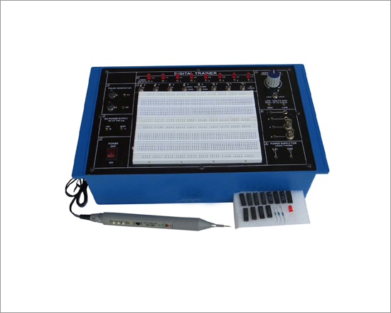
Code:EET0601
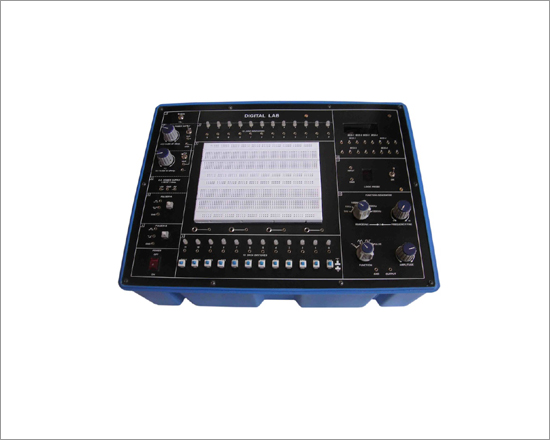
Digital Trainer is intended for elementary as well as advance training of Digital electronics and for bread board digital circuits, AND, OR, NOT, NAND, NOR, XOR, Three State Buffer, RS Latch, JK Flip Flop, Monostable Multibrator. and UP/ DOWN Counter.Practical experience on this board carries great educative value for R & D labs, Science and Engineering Students.
Specifications:
- Breadboard : Solderless Bread board with 1680 inter connected Tie Points
- Pulse Switches : 2 No's. Bounce free push buttons
- Logic Switches : 8 logic level Switches in Dip type .
- Power Supply : Fixed: +5V at 750 mA
- Power Sockets : Logic Probe Power Supply Sockets
- Logic Input : 8 LED buffered logic level indicators
- Variable Clock : Fine adjustment of clock frequency. Clock range selection L: 10 - 40 Hz, H : 1K - 20K Hz.
- Jacks : 2mm to BNC Socket 2 No. 2mm to 4mm Socket 2 No.
- Components Provided : ICs - 4001/1, 7400/3, 7402/1, 7404/1, 7408/1, 7432/1, 7476/2, 7486/1, 74126/1, Resistors 1/4W ±5% 230E/1, 10K/1, 39K/1, LED 5mm/1
- Accessories : Mains cord, 2mm Red & Black patch cords 5 each and 2mm to 1mm Red & Black 5 each
- Instruction manual : Strongly supported by detailed operating instructions.
- Logic Probe Omega Type LP-002 With 2mm Banana Pin Qt.1 Provided
- Wiring of all types of experiments become simple and less time consuming.
- The unit is operative on 230V ±10% at 50Hz AC Mains.
- Weight : 3 Kg. (Approx.)
- Dimension : W 340 x H 110 x D 210
Experiment Coverage:
- 1. LED Display
- Getting a Pulse
- Setting a Logic Level
- Getting a Clock and using the Logic Probe
- AND Gate (static operation)
- OR Gate (static operation)
- Dynamic Operation of AND Gate and OR Gate
- NOT Gate
- NAND Gate
- NOR Gate
- Exclusive OR Gate (Also called XOR Gate)
- XNOR
- Three State Buffer
- RS Latch
- Basic JK Flip Flop
- Monostable Multivibrator
- Asynchronous UP/DOWN Counter
Specifications of Logic Probe
- OPERATING VOLTAGE : 5V ± 3% regulated DC at 150mA, Ripple < 3mV.
- LOGIC STATE INDICATIONS
- High Level '1' : 'H' (HIGH).
- Low Level '0' : 'L' (LOW).
- Open / Floating state : 'O' (OPEN).
- Pulses : 'P' (PULSES).
- LOGIC FAMILIES : TTL / CMOS.
- FREQUENCY : Upto 50MHz for TTL/CMOS.
- RECOGNISED VOLTAGE LEVELS BY LOGIC PROBE AT
AN OPERATING VOLTAGE OF 5V ±3% RIPPLE < 3mV
- High Level Threshold : > 3.0V
- Low Level Threshold : < 0.8V
- Open/Floating Level : 0.8V to 3.0V (Approx.)
- Over Load Protection : Upto 25V source
- Sink Current : Less than 15mA
- SUPPLY CURRENT TAKEN
- BY THE PROBE : Less than 150mA
- SHORTEST PULSE WHICH CAN
- BE DETECTED BY THE PROBE : 40 nano Sec.
- Pulse detection is retriggerable and hence continuous pulses or clock will be indicated by 'P'.
- Positive going pulse will be indicated by letter 'L' followed by letter 'P' and then 'L' again.
- Negative going pulse will be indicated by the letter 'H' followed by letter 'P' and then 'H' again.
- THE INDICATOR 'O' OCCURS IN TWO SITUATIONS
- When the probe tip is not connected to a test point
- When the test point is floating with a level lying between about 0.8V to 3V
Note: Specifications are subject to change. Order Code can be different from Manufacturer's Model No.
Logic Lab
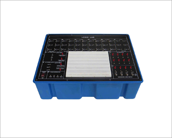
Code:EET0606
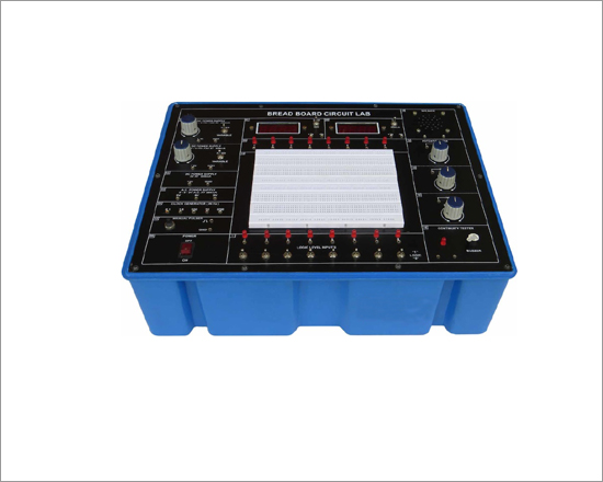
Logic Trainer is designed for the logic beginners to enhance the comprehension of basic logical theory. The digital lab covers regular digital circuits by solder-less interconnections on breadboard and as well as compitable with all optional modules through use of 2mm brass terminals and patch cords The design of the equipment is easy to operate and understand. It is equipped with various kinds of basic logic gates, debounced logical switches, LED indicators, DC power supply with short circuit protection, pulse generator and solderless bread board. The unit housed in attractive enclosure is supplied with mains cord, patch cords, Instruction manual.
Learners in high schools, Polytechnic Colleges and Universities, can use the trainer as independent activity tool.
Experimental Coverage:
- Logic gates operation
- To prove De-morgan's theorem with boolean logic equations
- Binary to Gray code conversion
- Gray code to Binary conversion
- Binary to Excess-3 code conversion
- Binary Adder and Subtractor
- Binary Multiplier
- EX-OR gate implementation
- Application of EX-OR gate
- To verify the dual nature of Logic Gates
- Study of Flip-Flops RS, JK,
Specifications:
- Basic Logic Gate Units : It contains 6 kinds of logic gates, i.e. AND GATE X 6, OR GATE X 6, NAND GATE X 6, NOR GATE X 6, XOR GATE X 3, NOT GATE X 3. Input voltage of Hl level > 2.25V Input voltage of LO level < 0.8V
- DC Power Supply : Equipped with short circuit protection and indicator.
- Output voltage +5V ± 5% Max. output current 1 Amp. Line regulation <50mV Load regulation<100mV
- Output voltage -5V ± 5% Max. output current 500 mA Line regulation <25mV Load regulation <30mV
- Output voltage ± 15V ± 5% Max. output current 500 mA Line regulation<150mV Load regulation <150mV
- Pulse Generator : 3 kinds of time interval, 1 sec, 0.1 sec, 0.01 sec.
- Output voltage +5V
- Debounced Logic Switch : 4 No's HI / LO
- LED Indicator : 8 Bits LED Output Indicator, Max. Input Voltage<= 15V DC
- Breadboard : Interconnected Solder less Breadboard having 2120 tie points, fitting all DIP sizes and all components with lead and solid wire AWG # 22-30 (0.3 - 0.8 mm)
- Accessories : Mains Cord, Instruction Manual,Red & Black patch cords (2mm with Pin) 10 each, Red & Black patch cord (Pin to Pin) 10 each. Wire 24/25 SWG. 1Meter each 5 Colour
- Weight : 5 Kg. (Approx.)
- Dimension : W412 x H 150 x D 310
Digital Lab Station
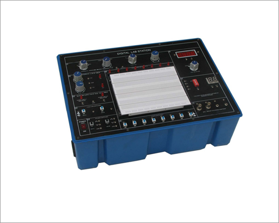
Code:EET0611
DIGITAL LAB STATION is designed for the logic beginners to enhance the comprehension of basic logical theory. The digital lab covers regular digital circuits by solder-less interconnections on breadboard and as well as compitable with all optional modules through use of 2mm brass terminals and patch cords The design of the equipment is easy to operate and understand. It is equipped with various kinds of basic logic gates, debounced logical switches, LED indicators, DC power supply with short circuit protection, pulse generator and solderless breadboard. The unit housed in attractive enclosure is supplied with mains cord, patch cords, Instruction manual.
Learners in high schools, Polytechnic Colleges and Universities, can use the trainer as independent activity tool.
Experimental Coverage:
- Logic gates operation
- To prove De-morgan's theorem With boolean logic equations
- Binary to Gray code conversion
- Gray code to Binary conversion
- Binary to Excess-3 code conversion
- Binary Adder and Subtractor
- Binary Multiplier
- EX-OR gate implementation
- Application of EX-OR gate
- Johnson Counter
- To verify the dual nature of Logic Gates
- Study of Flip-Flops RS, JK, D&T
- Multiplexer and Demultiplexer
- 4 Bit Binary up and down counter
- Study of 8 to 3 Line Encoder
- Study of 3 to 8 Line Decoder
- Study of Shift Register (SIPO)
- CMOS-TTL Interfacing
- Study of Crystal oscillator
- Study of pulse stretcher circuit
- 4 Bit Ring Counter
- Modulo 12 Counter By Direct Clearing
- Decade counter
- Shift Register SISO and PIPO
- SOLDER LESS BREADBOARD : Interconnected nickel plated with a total of 2120 tie points in total, fitting all DIP sizes and components with lead and solid wire in diameter of AWG #22-30 (0.3 - 0.8mm)
- DC POWER SUPPLY : Variable DC power :
- Positive output voltage: 0 to +15V
- Negative output voltage: 0 to -15V
- Maximum output current: 300 mA
- Line regulation: <0.05%/V (Ta=25°C)
- Load regulation: <30 mV (Ta=25°C)
- Fixed power supply:
- Positive output voltage: 5V ± 0.25V
- Maximum output current: 1 Amp
- Line regulation: <50 mV
- Load regulation: <100 mV
- Negative output voltage: -5V ± 0.25V
- Maximum output current: 100 mA
- Line regulation: <25 mV
- Load regulation: <30 mV
- All DC Power Supplies are equipped with
- short circuit protection
- FUNCTION GENERATOR : Frequency ranges:
- 1Hz - 11Hz
- 10Hz - 110Hz
- 100Hz - 1K1KHz
- KHz - 11KHz
- 10KHz - 110KHz
- Sine wave output: 0 to 8 Vp-p variable
- Triangle wave output: 0 to 6 Vp-p variable
- Square wave output: 0 to 8 Vp-p variable
- DIGITALVOLTMETER : 3 1/2 digits LED display 4 ranges:
- 199.9V full scale
- 19.99V full scale
- 1.999V full scale
- 199.9mV full scale
- Input impedance: 10 Meg. Ohm for any range
- TWO DIGIT SEVEN SEGMENT LED DISPLAY COMMON CATHODE
- FOUR POINTTIP/ BANANA SOCKET / BNC SOCKET EXCHENGE ADAPTERS
- EIGHT BUFFERED LED DISPLAY
- EIGHT DATA SWITCH
- TWO FUNCTION SWITCHES
- TWO PULSE SWITCH
Digital Electronic Trainer
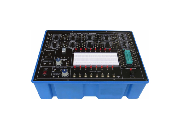
Code:EET0626
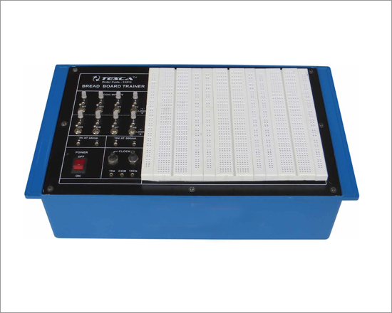
The Digital Electronic Trainer is intended for elementary as well as advance training of digital electronics. The trainer cover regular digital circuits by solder less inter connections through use of 2 mm brass terminations and patch cords. Various clock generators, logic level input / output indicators and DC regulated power supply are in built. The unit housed in sunmica finished wooden box enclosure with provision for safe keeping of mains cord, patch cords and top lid for protection during storage.
The Trainer CoverThe Following Experiment :
- Study of basic gates and verification of their truth tables:
- NOT
- OR
- AND
- NOR
- NAND
- EX-OR
- EX -NOR
- Study and verifications of the law of Boolean algebra and De-Morgan's Theorems.
- Study of important TTL terminologies. Verification of important TTL Circuit parameters.
- Construction and verification of various types of flip - flops using gates and Ic's :
- RS Flip-flop
- J-K Flip-flop
- Flip-flop
- T Flip-flop
- Construction and verification of various types of combinational circuits :
- Half Adder
- Full Adder
- Half Subtractor
- Full subtractor
- Even / Odd Parity Checker
- Multiplexer
- Demultiplexer
- Binary to Gray Converter
- Gray to Binary Converter
- 2 Bit Comparator
- Construction and verification of various types of counters :
- Down Counter
- 3 Bit Synchronous Ripple UP Counter
- 3 Bit Asynchronous Ripple UP Counter
- Ring Counte
- Decade Counter
- Decade Counter using IC 7490
- Construction and verification of 4 Bit Universal Shift Register :
- Parallel Input Parallel Output( Parallel load operation)
- Shift Right Operation (Serial Input serial Output)
- Shift Left Shift Register
- Study of 7 - Segment Display And Decoder / Driver.
- Many other experiments are possible using the onboard components and Bread board .
Features:
- Breadboards : Unique solder - less large size, spring loaded breadboard consisting of one Terminal Strips with 640 tie points each and 2 Distribution Strips with 100 tie points each, totaling to 840 tie points. (size:55mm X 170mm approx ).
- DC Power Supply : 5 V ± 0.25V / 500 mA ( IC based regulated output ).
- Clock Generators : i. Fixed : a. 0.1Hz b. 1Hz. ( Simultaneous independent outputs ).
- ( TTL, 5V ) : ii. Variable : One low frequency variable clock generator.
- Manual Pulser : One independent bounce less manual pulser ( useful for freezing the action of each stage of the counter after every clock pulse ).
- Logic Level Inputs : Eight independent logic level inputs to select High / Low TTL levels, each with a LED to indicate high / low status and termination.
- Logic Level : Eight independent buffered logic level indicators for High / Low status
- Indicators : indication of digital outputs.
- Seven segment decoder : One BCD to Seven Segment Decoder/ Driver IC with terminations.
- Continuity Tester : Audio / Visual indication.
- ZIF socket : IC's up to 40 pin Universal ZIF Socket ( without soldering)
- Potentiometer : One Potentiometer ( 100K ) with terminations.
- Power ON : Power ON switch with indicator for mains on indication and fuse for protection.
- Patch Cords : Set of 20 assorted coloured multi-stand wires with 2mm stackable plug termination at both ends.( Stackable )
- Power Requirement : 230V + 10% single phase AC.
- Instruction manual : One detailed instruction manual with well thought out experiments covering the above topics.
- Weight : 5 Kg. (Approx.)
- Dimension : W 412 x H 150 x D 310
Digital Logic Trainer

Code:EET0631
Digital Logic Trainer (TTL) / Logic Trainer Board based on 74 series has been designed specifically to make the students familiar with the study of TTL ICs and verification of the truth table of logic gates, flip-flops, Gated & Master Slave JK flip-flops, Schmitt Trigger, Expanders , Binary address, Counters, Shift registers, Multiplexer (Encoder), Demultiplexer (Decoder), 8 Bit D/A Converter and 8 Bit A/D Converter etc. Large area of Bread Board is provided on the front panel for ICs. Students can make the circuit easily on the Bread Board with the help of other accessories which are provided on the front panel of Digital Logic Trainer.
Practical experience on this trainer/board carries great educative value for Science and Engineering Students.
Specifications:
- OUTPUT D.C. VOLTAGE : Fixed 5V and 0 - ±18V.
- OUTPUT CURRENT: 1 Amp.
- LOAD REGULATION : ± 1% of the highest specified output voltage. (NO LOAD TO FULL LOAD)
- RIPPLE AND NOISE : less than 2 mV.
- VARIABLE CLOCK FREQUENCY : 1 Hz to 1 MHz by three frequency range & multiplier.
- LOGIC INPUTS : 16 switches for High/Low
- OUTPUT INDICATORS : 16, 5 mm bright Red LEDs.
- SEVEN SEGMENT DISPLAY : 4 digit seven segment display with decoder driver.
- DIGITAL VOLTMETER : Digital DC voltameter range 0 - 20V.
- OPERATING CONDITIONS : 0 to 40°C and 95% R.H. at 40°C.
- BREAD BOARD : Unique solder - less large size, spring loaded breadboard consisting of 2 Terminal Strips with 640 tie points each and 4 Distribution Strips with 100 tie points each, totalling to 1680 tie points
- INPUT VOLTAGE : 230V ±10% at 50 Hz A.C. Mains.
- ICs PROVIDED : 29 ICs have been provided.
Note :Following ICs or equivalent can be provided.
| S.NO |
LOGIC I.C. NO. |
QTY. |
| 01 |
QUAD 2-INPUT NAND GATE 7400 |
1 |
| 02 |
QUAD 2-INPUT NOR GATE 7402 |
1 |
| 03 |
HEX INVERTER 7404 |
1 |
| 04 |
QUAD 2-INPUT AND GATE 7408 |
1 |
| 05 |
DUAL 4-INPUT NAND SCHMITT TRIGGER 7413 |
2 |
| 06 |
QUAD 2-INPUT OR GATE 7432 |
1 |
| 07 |
EXPENDABLE DUAL 2-WIDE 2-INPUT AOI GATE 7450 |
2 |
| 08 |
DUAL 4-INPUT EXPANDER 7460 |
2 |
| 09 |
EDGE - TRIGGERED FLIP-FLOP 7470 |
1 |
| 10 |
DUAL JK M/S FLIP-FLOP 4027 |
2 |
| 11 |
DUAL JK-FLIP-FLOP 7473 |
2 |
| 12 |
4 BIT FULL ADDER 7483 |
1 |
| 13 |
QUAD 2-INPUT EXCLUSIVE OR-GATE 7486 |
1 |
| 14 |
DECADE COUNTER 7490 |
3 |
| 15 |
DIVIDE-BY-TWELVE COUNTER 7492 |
1 |
| 16 |
4-BIT BINARY RIPPLE COUNTER 7493 |
1 |
| 17 |
4-BIT SHIFT REGISTER 7495 |
1 |
| 18 |
QUAD 3-STATE BUFFER 74126 |
1 |
| 19 |
8-INPUT MULTIPLEXER 74151 |
1 |
| 20 |
1-OF-16 DECODER/DEMULTIPLEXER 74154 |
1 |
| 21 |
8-BIT D/A CONVERTER DAC 0808 |
1 |
| 22 |
8-BIT A/D CONVERTER ADC 0808 |
1 |
* Strongly supported by detailed Operating Instructions, giving details of Object, Theory, Design procedures, Report Suggestions and Book References.
Digital Logic Trainer (cmos) / Logic Trainer Board (based On 74 C/4000 Series)
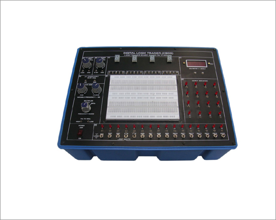
Code:EET0636
Digital Logic Trainer (CMOS) / Logic Trainer Board based on 74 C/4000 series has been designed to make the students familiar with the study of CMOS ICs and verification of the truth tables of logic gates, flip-flops, Gated & Master Slave JK flip-flops, Schmitt Trigger, Expanders , Binary address, Counters, Shift registers, Multiplexer (Encoder), Demultiplexer (Decoder), 8 Bit D/A Converter and 8 Bit A/D Converter etc. Large area of Bread Board is provided on the front panel for ICs. Students can make easily the circuit on the bread board with the help of other accessories which are provided on the front panel of Digital Logic Trainer. The logic trainer board is quite educative and is a must for Science and Engineering Students.
Specifications:
- OUTPUT D.C. VOLTAGE : Fixed 5V, Variable 0 to ±18 V.
- OUTPUT CURRENT: 1 Amp.
- LOAD REGULATION : ±1% of the highest specified output voltage. (NO LOAD TO FULL LOAD)
- RIPPLE AND NOISE : less than 2 mV.
- VARIABLE CLOCK FREQUENCY : 1 Hz to 1 MHz by three frequency range & multiplier.
- LOGIC INPUTS : 16 switches for High/Low
- OUTPUT INDICATORS : 16, 5 mm bright Red LEDs.
- SEVEN SEGMENT DISPLAY : 4 digit seven segment display with decoder driver.
- DIGITAL VOLTMETER : Digital DC voltameter range 0 - 20V.
- OPERATING CONDITIONS : 0 to 40°C and 95% R.H. at 40°C.
- BREAD BOARD : Unique solder - less large size, spring loaded breadboard consisting of 2 Terminal Strips with 640 tie points each and 4 Distribution Strips with 100 tie points each, totalling to 1680 tie points.
- INPUT VOLTAGE : 230V ±10% at 50 Hz A.C. Mains.
- ICs PROVIDED : 29 ICs have been provided.
| S.NO |
LOGIC I.C. NO. |
NO. |
QTY. |
| 01 |
QUAD 2-INPUT NAND GATE 74C00 |
74C00 |
1 |
| 02 |
QUAD 2-INPUT NOR GATE |
74C02 |
1 |
| 03 |
INVERTER CIRCUIT |
4069 |
1 |
| 04 |
QUAD 2-INPUT AND GATE |
74C08 |
1 |
| 05 |
QUAD 2-INPUT NAND SCHMITT TRIGGER |
4093 |
2 |
| 06 |
QUAD 2-INPUT OR GATE |
74C32 |
1 |
| 07 |
DUAL 2-WIDE 2-I/P AOI GATE |
4085 |
2 |
| 08 |
3-STATE EXPENDABLE 8-FUNCTION 8-INPUT GATE |
4048 |
2 |
| 09 |
DUAL J-K POSITIVE EDGE TRIGGERED FLIP-FLOP |
7470 |
1 |
| 10 |
DUAL JK M/S FLIP-FLOP |
4027 |
2 |
| 11 |
DUAL J-K F-F WITH CLEAR |
74C73 |
2 |
| 12 |
4-BIT BINARY FULLADDER |
74C83 |
1 |
| 13 |
QUAD 2-INPUT EX-OR GATE |
4070 |
1 |
| 14 |
4-BIT DECADE COUNTER |
74C90 |
3 |
| 15 |
DIVIDE-BY TWELVE COUNTER |
74LS92 |
1 |
| 16 |
4-BIT BINARY COUNTER |
74C93 |
1 |
| 17 |
4-BIT RIGHT-SHIFT/LEFT-SHIFT REGISTER |
74C95 |
1 |
| 18 |
TRI-STATE QUAD BUFFERS |
74C126 |
1 |
| 19 |
8-CHANNEL DIGITAL MULTIPLEXER |
74LS151 |
1 |
| 20 |
4-LINE TO 16-LINE DECODER/ DEMULTIPLEXER |
74C154 |
1 |
| 21 |
8-BIT D/A CONVERTER DAC |
0808 |
1 |
| 22 |
8-BITA/D CONVERTOR ADC |
0808 |
1 |
* Strongly supported by detailed Operating Instructions, giving details of Object, Theory, Design procedures, Report Suggestions and Book References.
* Weight : 5 Kg. (Approx).
* Dimension : W 412 x H 150 x D 310
Digital IC Trainer (TTL) (for Verification of Truth Table of Logic Gates)
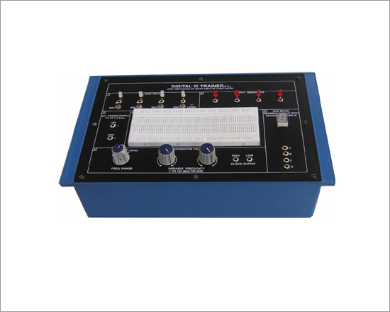
Code:EET0641
Digital IC Trainer (TTL) has been designed for verification of the truth table of logic gates and address etc. Students can be trained about the digital ICs by using this board. The fundamentals of the digital ICs can easily be understood by performing required experiments for verification of truth table of logic gates. Quite large area of the bread board has been provided on the panel for ICs. Students can make the circuits easily on the bread board with the help of other accessories which have been provided on the panel.
Practical experience on this board carries great educative value for Science and Engineering Students.
Specifications :
- OUTPUTD.C. VOLTAGE : Fixed 5V ±1%.
- OUTPUTCURRENT : 1.5 Amp.
- LOAD REGULATION : ±1% of the highest specified output voltage.(NO LOAD TO FULL LOAD)
- RIPPLE AND NOISE : less than 5 mV.
- VARIABLE CLOCK FREQUENCY : 1 Hz -100 Hz 100 Hz -10 KHz 10 KHz - 1 MHz
- LOGIC INPUTS : Four switches for High/Low.
- OUTPUTINDICATORS : Two 5 mm bright Red LEDs.
- SEVEN SEGMENT DISPLAY : "Common Anode" type Red LED.
- BREAD BOARD : Half main strip for connections & : One full main strip each set for ICs.
- OPERATING CONDITIONS : 0 to 40°C and 95% R.H. at 40°C.
- LOGIC GATES PROVIDED : OR (7432), AND (7408), NOT (7404) NAND (7400), NOR (7402) & EX-OR (7486)
- EXTRAFEATURES : Other ICs can also be used to perform required experiments with any gates/address etc.
- INPUT VOLTAGE : 230 V ±10% at 50 Hz A.C. Mains.
- Weight : 3 Kg. (Approx).
- Dimension : W 340 x H 110 x D 210
- Strongly supported by detailed Operating Instructions, giving details of Object, Theory, Design procedures, Report Suggestions and Book References
Logic Gates Circuit Trainer (educational Training Laboratory)
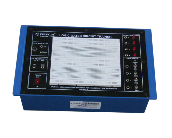
Code:EET0651
Logic Gates Circuit Trainer offers a unique entry into the world of microelectronics. The system combines simple, easy to use, ICs for various gates and flip-flops, power supply, clock input and output state with a versatile solderless bread board area. Students new to digital electronics can implement logic circuits in a matter of minutes on the bread board area. As confidence grows the student will naturally progress for using more complex logic ICs on the large bread board area. This unique approach enables the unit to be used by the absolute beginner, yet it may also be usefully employed in advanced project work. The many outstanding features of the logic trainer, combined with its ease of use and robust housing, make it the first choice for those wishing to introduce students to digital electronics for the first time.
Practical experience on this board carries great educative value for Science and Engineering Students.
Specifications:
- OUTPUT D.C. VOLTAGE : Fixed 5V ±1%
- OUTPUTCURRENT : 1 Amp.
- LOAD REGULATION : ±1% of the highest specified output voltage.(NO LOAD TO FULL LOAD)
- LINE REGULATION (For ±10% change : less than 50 mV. in mains Voltage i.e. 230V)
- RIPPLE AND NOISE : less than 5 mV.
- CLOCK INPUT DEVICE : Clock pulse of 1 second.
- DEBOUNCED LOGIC SWITCH (HI/LO) : Four nos. Input voltage of HI level ' 2.25V. Input voltage of LO leve £ l 0.8V.
- 4 BITS LED OUTPUT INDICATOR : Maximum input voltage less than or equal to 5V D.C.
- SOLDER LESS BREAD BOARD : Bread Board having one main strip, total interconnected 640 tie points for ICs and half main strip, total interconnected 320 tie points for power supply, Clock, Input and output state. Each strip having length 173mm and accepting dia 0.56mm/24SWG recommended, use only 22-26 SWG wire for interconnections.
- BASIC LOGIC GATES & : Four AND gates, Four OR gates, Four NAND gates, Four NOR gates, Six NOT FLIP FLOP UNITS gates, Dual J-K flip-flop, J.K. master/slave flip-flop & Dual D-type flip flop.
- APPLICATIONS : Verification of AND, OR, NOT, NAND, NOR Gates & their truth table. Verification of Boolean Algebra. The half-adder and full-adder design. Verification of D-type flip-flop and truth table. Verification of JK flip-flop and truth table. Verify cation of Dual JK Master/Slave flip-flop and truth table.
Features:
- The unit is operative on 230V ±10% at 50Hz A.C. Mains.
- Strongly supported by detailed Operating Instructions, giving details of Object, Theory, Design procedures, Report Suggestions and Book References.
- Weight : 3 Kg. (Approx). Dimension : W 340 x H 110 x D 210
Optional Accessories :
- Jumper wire bag (4 reels, 5M/reel),Cutter/Stripper tool.
NOTE : Bulk order for above Trainer has been received against International Competitive Bidding (InCB) under World Bank Project for Technical education.
Electricity Trainer
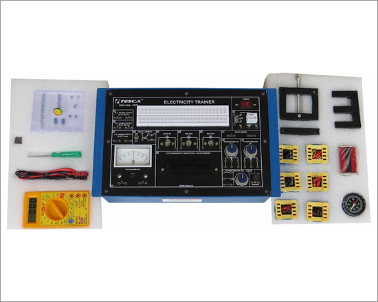
Code:EET0656
'Electricity Trainer' is a versatile training kit for a laboratory. It is designed such that all the basic electrical circuits can be tested with the help of this trainer kit. The experiments given with training system develop mental starting from an introduction to the circuit, basic fundamentals and complete circuits like series and parallel circuits, electromagnetic induction, coil behaviors with AC and DC circuits diode and transistor characteristics etc. This simple training kit provides a strong foundation for future studies in electrical or electronics. This takes students from the basic of ohm's law, through simple series and parallel circuit analysis and into same elementary aspects of electronics where they will build circuits using capacitors, transistor and diodes. Student can study how the resistance of a light bulb filament changes as it heats up. With this system a set of coils and cores are provided- These high quality coils and laminated iron cores provides an effective introduction to electromagnetic theory. Each coil is labeled with number of turns. These can be used in study of The Equipment is Useful for Students at level in engineering / technical institutes (EC & Telecom) Technical training centers in communication organizations, R&D personal and practicing engineering in research labs and industry.
Object:
Experiments that can be performed
- To study the Resistances individually, as well as in series and in parallel connections.
- To study the ohm's law mathematical relation ship between three variables voltage (V), current (I) and resistance (R).
- To study the voltage and current flowing into the circuit.
- To study the behavior of current when light bulbs are connected in series/parallel circuit.
- To study the Kirchoff's Law for electrical circuits
- To study the R-C circuit and find out the behavior of capacitor in a R-C network and study the phase shift due to capacitor.
- To study the L-C circuit and its oscillations.
- To study the characteristics of a semiconductor diode.
- To study the characteristics of a transistor.
- To understand the Faraday's Law of electromagnetic induction.
- To study the behavior of current when inductance is introduced in the circuit.
- To study the Lenz's Law and effect of eddy current.
- To study the relay and construct a switching circuit by using relay
- To study the Oersted experiment.
- To study the phenomenon of mutual induction.
- To construct and study the step down transforn1er with the help of given coils and cores.
- To construct and study the step up transformer.
- To study the effects of moving I core on a step up transformer.
- To convert a galvanometer into voltmeter.
- To convert a galvanometer into ammeter.
Specification & Features:
- DC power Supply : 5V. 200 mA
- DC power Supply : 12V. 200 mA
- AC power Supply : 6V, lA
- Relay : 12V
- Galvanometer : 30 -0 -30 .
- Galvanometer Resistance : 80 Ohm
- Light Bulbs (3 Nos.) : 6V
- Potentiometers (3 Nos.) : 25 Ohm. 1 W 10 K Ohm. 1 W
- Switch : 1 Pole, 2 Way Toggle Type
- Core Types : E, I, U
- Main Supply : 230V AC 50Hz
- Dimension : W 340 x H 110 x D 210
COILS
Note: Specifications are subject to change. Order Code can be different from Manufacturer's Model No.
Electricity Lab
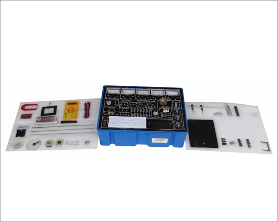
Code:EET0661
"Electricity Lab" is a versatile training kit for a laboratory. It is designed such that all the basic electrical circuits can be tested with the help of this trainer kit. The experiments given with training system develop mental starting from an introduction to the circuit, basic fundamentals and experiments on Ohm's Law, Magnetism, Relay, Power, Lenz's Law, Motors, Diode, Kirchoff's Law, R, L, C and many more. This simple training lab provides a strong foundation for future studies in electrical or electronics. This takes students from the basic of ohm's law, through simple series and parallel circuit analysis and into same elementary aspects of electronics where they will build circuits using capacitors and diodes. With this system a set of coils and cores are provided. These high quality coils (Labeled with number of turns) and laminated iron cores provides an effective introduction to electromagnetic theory.
Specifications:
- Meters: 5 Nos.
- AC Voltmeter : 15V
- DC Voltmeter :
- 15V
- Galvanometer : ± 250uA
- DC Ampere Meter : 0.6Amp
- DC Ampere Meter : 5A
- Power Supply:
- Power Supplies : 3, 6, 12Vat 3.5A
- Power SupplyAC : 30Vat1A
- Power SupplyDC : 5Vat100mA
- Switch SPDT
- Switch DPDT
- Push switch
- Logic Switches Two No. Push type
- Relay 12VDCOne change over
- Buzzer/Electric Bell
- Transformer Input 6-0-6V and Output 6-0-6V
- Bulb6VThree Nos.
- Resistance 1E2/1W, 5E/5W, 50E/5W,100E/5W, 220E/2W, 470E/2W, 1K/1W, 100K/1W
- Capacitance 1000MFD/25VTwo Nos.
- Diode IN4007Two Nos.
- LED5mm
- Thermocouple
- Potentiometer 10K
- Breadboard 840Tie Points
- Fuse Holder open type
- Electromagnetic Induction&Transformer
- Main Supply 230VAC, 50 Hz
Accessories:
- Beaker 100ml - 1 No.
- Patch Cords/ Connecting Leads - 12No s.
- Rods/ Strips for - 1 No. each Copper, Tin, Al, Zinc, Glass Brass, Carbon, Iron, Acrylic, Lead, Stainless Steel
- Magnets - 3Nos.( Bar Type-2, Horseshoe (U) type-1)
- Coils - 1 No. 100 and 200 Turns
- Crocodile Clips - 1 No. red and black
- Battery/ Cell with holder - 2 Nos. 1.5 V
- Glass Fuses - 10 Nos. 0.5A
- Compass - 1 No.
- Measuring Scale - 1No.
- Insulated Disc - 1 No.
- Motor Assembly - 1 No. including Armature,Rotor, Brush, Motor Support,Iron Fillings
- Helix Assembly - 1 No.
- Meter Demonstration - 1 No.
- Core - 1 Set of U&I with Bolt
- Aluminium Ring - 1 No.
- Stand - 1 No. for motor action demonstration
- IC - AND (IC7408), OR (Ic7432), NOT (7404) And EX-OR Gate (IC7486)
- Multimeter - 1 No.
- Soft Iron Piece - 1No.
Experiment Coverage:
To Study/ Experiment the following:
- Electricity by Chemical Action
- Electricity by Heat
- Electricity by Magnets
- Conductors and Insulators
- Resistor Colour Code
- Resistors in series combination
- Resistors in Parallel combination
- Resistors in series and Parallel combination
- Ohm's Law
- Applying Ohm's Law
- Kirchoff's Current Law or Junction Rule
- Kirchoff's Voltage Law or Loop Rule
- Linear & Non Linear Resistance
- Measurement of Power
- AC & DC Power
- Fuses and Circuit Breakers
- Heating Effect & the Fuse
- Load in Series and Parallel Circuits
- Cells Connections
- Voltage in series & parallel Circuits
- Current in series and parallel Circuits
- Meter Movement
- Meters in a Circuit
- Charging and Discharging of Capacitors
- Study of Diode
- Full Wave Rectifier (optional)
- The Contactorv
- Study of Relay
- The Electric Bell
- Magnets and Magnetism
- Magnetic Field
- Magnetic Properties
- Magnetic Strength
- Magnetic field around a conductor
- Magnetic poles around a helix
- Electromagnetic Strength
- Electromagnetic Effect
- Lenz's Law
- Self Inductance
- . Mutual Induction
- Transformer Action
- Transformer Ratio of Voltages
- Transformer Phasing
- Faraday's Law of Electromagnet Induction
- Motor Action
- The Electric Motor Generator
- Generation of DC
- Generation of AC
- Permanent Magnet DC Motor
- DC Series Motor
- DC Shunt Motor
- AC Universal Motor
- AND Logic Gate with truth table
- OR Logic Gate with truth table
- NOT Logic Gate with truth table
- X-OR Logic Gate with truth table
- Convert a Galvanometer into voltmeter
- Convert a Galvanometer into Ammeter
Power Electronics Lab

Code:EET0666
Power Electronics Lab is used to perform power electronics circuit experiments. It is very useful in power electronics laboratories for performingpower experiments in colleges and universities. It is very for student to know about the characteristics of power electronics devices and theapplications of power devices. The applications or power devices are in alarm circuit, lamp flasher, rectifiers, choppers, invertors. It is also usedfor commutation circuits.The Equipment is Useful for Students at level in engineering / technical institutes (EC & Telecom) Technical training centers in communicationorganizations, R&D personal and practicing engineering in research labs and industry.
Technical Specifications:
DC Power Supply on Board
- ± 5V at 100mA
- ± 12V at 150mA
- ± 15V at 50mA
- ± 35V at 50mA
AC Power Supply on Board : 18V - 0V - 18V at 50mA
- Triggering Circuit on Board : 5 gate signal output
- Frequency range : 40Hz to 900Hz Variable
- Amplitude : 12V PWM control of G1,G2,G3 and G4 Duty cycle control of "Gate" Signal is 0 to 100%
- Single Phase Rectifier : Firing angle control 0°-180° variables
- Firing Circuit on Board : Four gate signal output with isolation
- SCR Assembly : 4 SCRs 2P4M, 600V,2A
- Power Devices : IGBT-G4BC20S, MOSFET-IRF540, UJT-2N2646, DIAC-DB3, TRIAC-BT136, PUT-2N6027
Circuit Components On Board :
- Capacitor 0.01uF, 0.047uF , 0.1uF, 0.33uF, 1uF/63V(4Nos.) 2.2uF/50V
- Diode 1N4007 (8Nos.)
- Zener Diode 9V (1Nos. )
- Inductors 10mH, (1Nos.), 68mH (2Nos.)
- Load Resistance 120E, 270E, 1K, 2K2, each 5W
- Resistance on Board (½ W) 22E/5W, 100E/2W, 220E/2W
- Resistance on Board(1/4W) 10K (3Nos.), 22K,33K,47K,
- Potentio Meter 4K7(2Mos.), 1M(1Nos.)
- Pulse Transformer on Board : 2 Nos. PT4502, 1:1 and one is PT4503 1:1:1
- Toggle Switch : SPST (1Nos.)
- Power Requirements : 220V ±10%, 50Hz
Experiments On Board Using Breadboard:
- To study the characteristics of SCR and plot its V-I Characteristics
- To study the Gate control characteristics of SCR and It's graph
- To study the characteristics of UGT and calculate interbase resistance and intrinsic standoff ratio
- To study the characteristics of MOSFET.
- To study the characteristics of IGBT.
- To study the characteristics of DIAC and plot its V-I Characteristics curve.
- To study the V-I characteristics of TRIAC.
- To study the characteristics of PUT.
- To study of class B commutation circuit.
- To study of class C commutation circuit.
- To study of class D commutation circuit.
- To study of class F commutation circuit.
- To study the Resistor Triggering circuit.
- To study the Resistor-Capacitor Triggering Circuit (Half wave).
- To study the Resistor-Capacitor Triggering Circuit (Full wave).
- To study the triggering of SCR using UJT.
- To study the Triggering of SCR using 555 IC.
- To study the Triggering of SCR using Op-Amp 74I IC.
- To study of the ramp and pedestal triggering using anti-parallel SCR in AC load.
- To study of the UJT relaxation oscillator.
- To study of the voltage commutated chopper.
- To study of the Bedford inverter.
- To study of the single phase PWM inverter using MOSFET.
- To study of the single phase PWM inverter using IGBT.
- To study the half-wave controlled rectifier with resistive load.
- To study the half wave controlled rectifier with RL load.
- To study the full-wave controlled rectifier (mid-point configuration) with resistive load.
- To study the full-wave controlled rectifier (mid point configuration) with RL load.
- To study the fully controlled bridge rectifier with resistive load.
- To study the fully controlled bridge rectifier with RL load
Note: Specifications are subject to change. Order Code can be different from Manufacturer's Model No.
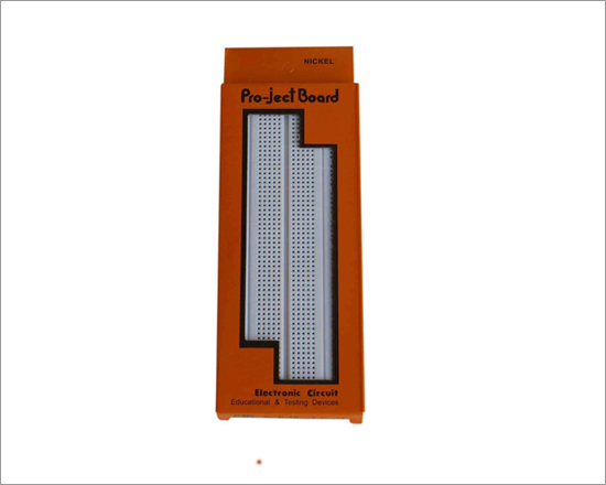
BreadBoard
Code:EET0671
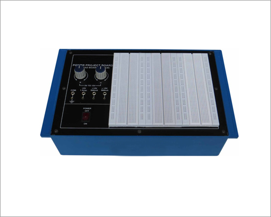
You just plug-in vertically your components in the position you want without soldering. The pro-jectboard will accept up, clock-clips, the smaller DIP's. Each unit will accept transistors, diodes, LEDS, resistors, capacitors, pots and virtually all types of components. The units are desired to use # 22-30 solid hookup wire for interconnection will plug-in ease. it could be combined with a series features a unique interlocking desired, without tools to meet changing requirements and components are reuseful.
- External Body is made of ABS.
- The internal interconnected clips are Nickel-Plated.
Features:
| S.No.Specifications |
Order Code EET0671a |
Order Code EET0671b |
Order Code EET0671c |
Order Code EET0671d |
| 01 |
Length |
172mm |
165mm |
172mm |
| 02 |
Width |
65mm |
54mm |
65mm |
| 03 |
Height |
10mm |
8.5mm |
10mm |
| 04 |
TIE Points |
840 |
830 |
840 |
| 05 |
5 Inter- connected Clip |
128 |
126 |
128 |
| 06 |
25 Inter- connected Clip |
8 |
8 |
8 |
| 07 |
IC Capacity 14 Pins |
9 |
9 |
9 |
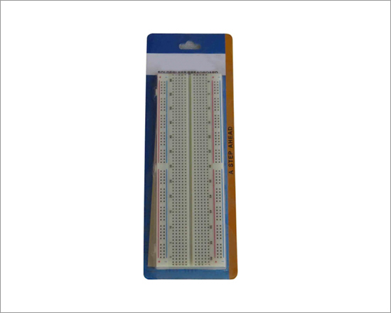
BreadBoard
Code:EET0676
You just plug-in vertically your components in the position you want without soldering. The pro-jectboard will accept up, clock-clips, the smaller DIP's. Each unit will accept transistors, diodes, LEDS, resistors, capacitors, pots and virtually all types of components. The units are desired to use # 22-30 solid hookup wire for interconnection will plug-in ease. it could be combined with a series features a unique interlocking desired, without tools to meet changing requirements and components are reuseful.
- External Body is made of ABS.
- The internal interconnected clips are Nickel-Plated.
Features:
| S.No.Specifications |
Order Code EET0676a |
Order Code EET0676b |
Order Code EET0676c |
Order Code EET0676d |
| 01 |
Length |
172mm |
165mm |
172mm |
| 02 |
Width |
65mm |
54mm |
65mm |
| 03 |
Height |
10mm |
8.5mm |
10mm |
| 04 |
TIE Points |
840 |
830 |
840 |
| 05 |
5 Inter- connected Clip |
128 |
126 |
128 |
| 06 |
25 Inter- connected Clip |
8 |
8 |
8 |
| 07 |
IC Capacity 14 Pins |
9 |
9 |
9 |
BreadBoard
Code:EET0681
You just plug-in vertically your components in the position you want without soldering. The pro-jectboard will accept up, clock-clips, the smaller DIP's. Each unit will accept transistors, diodes, LEDS, resistors, capacitors, pots and virtually all types of components. The units are desired to use # 22-30 solid hookup wire for interconnection will plug-in ease. it could be combined with a series features a unique interlocking desired, without tools to meet changing requirements and components are reuseful.
- External Body is made of ABS.
- The internal interconnected clips are Nickel-Plated.
Features:
| S.No.Specifications |
Order Code EET0681a |
Order Code EET0681b |
Order Code EET0681c |
Order Code EET0681d |
| 01 |
Length |
172mm |
165mm |
172mm |
| 02 |
Width |
65mm |
54mm |
65mm |
| 03 |
Height |
10mm |
8.5mm |
10mm |
| 04 |
TIE Points |
840 |
830 |
840 |
| 05 |
5 Inter- connected Clip |
128 |
126 |
128 |
| 06 |
25 Inter- connected Clip |
8 |
8 |
8 |
| 07 |
IC Capacity 14 Pins |
9 |
9 |
9 |