Consumer Electronics Trainers


Facsimile Dynamic Demonstrator

Code:EET1086

Description :

Facsimile Demonstrator is a complete educational system designed to give a clear accurate and realistic in-sight into the working of the Fax Trainer. This trainer is designed on CAD system and the specifications are given below:

  • Housing : It is housed in an elegant metal cabinet
  • Dimension : 82cms x 19cms x 48cms
  • Weight : (Approx.) 15KGS
  • Power : 230VAC - Mains operated

Specifications

  • Type :Desktop Transceiver
  • Applicable Line : Public Switched Telephone Network
  • Compatibility : CCITT Group 3
  • Scan Method :Horizontal -Contact Image Sensor,Vertical-intermittent Scanning by stepper Motor
  • Document Size : Max - 216 X 1 000 mm , Min - 70 X 120 mm
  • Document Thickness : 0.06 - 0.15 mm
  • Print Method : 0.06 - 0.15 mm
  • Print Method : Thermal Printing
  • Recording Paper Size : 216 mm X 15M, outer diameter=40mm
  • Recording Width : 216 mm
  • Resolution :
    - Horizontal - 8 dots/mm
    - Vertical - Standard Mode - 3.85 lines/mm
    - Fine mode - 7.7 lines/mm
  • Coding Scheme : MH
  • Modem : V.29, V.27ter with fall back function
  • Modem Speed : 9600/7200/4800/2400 bps(automatically fall back)
  • Power Supply: Single phase 22OV, model:180-260V AC, 50/60Hz, Single phase
  • Power Consumption : Standby: 6W ,Max: 90W
  • Operating Environment : Temperature: 5-400 C (41-950F) ,Humidity: 45-85%

Telephone Trainer

Code:EET1091

Telephone Trainer is complete working model of telephone. It gives hands on experience on basic telephony concepts, working and different experiments on telephone.The trainer comes complete with exhaustive experiment manual, accessories, test points, and LED's for indication. The complete circuit is printed on single sided PCB in section wise format, depicting the complete flow of system. Practical experience on this trainer carries great educative value for Science & Engineering Students.


Experiments:

  • Understanding of telephone.
  • Study of telephone features.
  • Study of speech circuit.
  • Study of ringer.
  • Study of tone dialing.
  • Study of pulse dialing.
  • Study of switching mechanism between subscriber :-
    - Incoming call.
    - Outgoing call.

Features:

  • Single sided PCB depicting different working sections.
  • 35 test points and LED's provided on board to study signals.
  • Power from external telephone line, no power supply is required.
  • Pulse dialing as well as tone dialing facility.
  • Dialer and ringer section.
  • Mute, Redial and ON / OFF hook switches.
  • Telephone Handset: 1 Nos.
  • Weight : 4 Kg. (Approx.)

Technical Specifications :

  • Line in section : One dot line connection port.
  • Handset : One handset connection port.
  • Keyboard : 4x3 matrix keyboard.
  • Dialer : Tone and pulse.
  • Facilities : Redial up to 32 digits, Mute, Redial, Flash, Pause switches.
  • Indicators : Line in, Hook, tone and ringer, Call mute section.
  • Control : Ringer volume control, Ringer speed control.
  • Speech path : Fully Non-Blocking.
  • Dial pulse ratio : 10 pps + / - 10%.
  • Tone frequency : 430 Hz.
  • Input power : From telephone line.

Test Points:
01. 35 No. of TP's test points are provided on board to observe intermediate signals.

  • Good Quality, reliable terminal/sockets are provided at appropriate places on panel for connections / observation of waveforms.
  • Strongly supported by detailed Operating Instructions, giving details of Object, Theory, Design procedures, Report Suggestions and Book References.

PA ( Public Address ) System Trainer

Code:EET1096

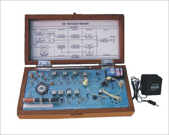
This Trainer has been designed with a view to provide practical and experimental Knowledge of general circuit of PA (Public Address) System Trainer on Single P.C.B. of size 300 x 400mm".

Practical experience on this Trainer carries great educative value for Science & Engineering Students.

Object:

  • To study the circuit & operation of a PA system and observe various intermediate waveforms.

Features:

The P.A. System Trainer consists of :
  • The complete circuit of a public address amplifier is printed on a single PCB.
  • All part are soldered on PCB.
  • Explanation, Observation, Alignment and adjustment of internal and external control possible due to single PCB.
  • Easy identification of different parts is possible at a glance.
  • Easy measurement of voltages and observation of waveforms at any point. Also typical voltages and waveforms are provided.
  • A manual having practical detail is provided with the trainer.
  • The whole circuit of public address amplifier is explained sectionwise in the manual.

Technical Specifications :

  • Signal to noise ratio : 60 dB.
  • Frequency response : 100 Hz to 15000 Hz.
  • Amplifier with two mic. inputs.
  • One mic. & One Aux. inputs.
  • Power supply : 220VAC 50 Hz.
  • Power Output : 80 Watt RMS Max.
  • Tone control : Bass, Treble.
  • Audio Monitoring Indicators.
  • Output Tap for speaker matching : 4, 8 &16 Ohms.


* Good Quality,reliable terminal/sockets are provided at appropriate places on panel for connections / observation of waveforms.
* Strongly supported by detailed Operating Instructions, giving details of Object, Theory, Design procedures, Report Suggestions and Book Reference

Other Apparatus Required:

  • Digital multimeter Order Code - 16901
  • Cathode Ray Oscilloscope dual trace

Accessories:

  • Three Mic. with lead & connector
  • One speaker 4 Ohm, 4 Watt provided for normal operation

Mobile Phone Trainer

Code:EET1101

MOBILE PHONE TRAINER kit has capability of full duplex mobile communication. Provides basic theory and working fundamentals of a 2G hand set based on the NOKIA 3310/3315. This trainer kit designed with a view to provide network, power supply, charging & user interface circuits for their practical and theoretical study based on NOKIA 3310/3315. Practical experience on this board carries great educative value for Science and Engineering Students.

Features:

  • Real time Mobile Operation
  • Expanded and open trainer
  • Full understanding of mobile phone working
  • Frequency measurement and band verification
  • Provides study of all sections in mobile phone
  • TX/RX Frequency measurements
  • 2G technology & GMSK signals
  • GSM data rate
  • Detail study of User Interface Control signals
  • Detail study of SIM Operation
  • Battery identification and charging study
  • Switch Faults

Technical Specifications :

  • Cellular System : EGSM/GSM 900
  • Rx Frequency Band : EGSM 925, 960MHz: GSM 900, 935, 960MHz
  • Tx Frequency Band : EGSM 880, 890MHz: GSM 900, 890, 915MHz
  • Output Power : +5V, +33dBm/32mW, 2W
  • Channel Spacing : 200 KHz
  • Antenna : Loop type, 50W
  • Display : 84 x 48 pixels
  • On Board sections : Antenna, Keypad, SIM, Charging Circuit, Clock, User interface such as Buzzer, Vibrator, LEDs.
  • No. of test points : 54
  • No. of switched fault : 20
  • Features that can be set : Screen savers, Ring tones, Logos, SMS etc.
  • Accessories included : Battery, Mains cord, Manual, Hands Free Kit
  • Power Requirement : 220V ± 10% 50 Hz
  • Power consumption : 3.6 Watts (Approx)
  • Fuse : 1.5 amps

Experiments That Can Be Performed:

  • To study and measure the GMSK signals such as Tx.1/ QRx1/Q
  • To study and observe the system CLK
  • Observation of Audio signal
  • To study and measure the power supply
  • Study of charging phenomena with fault insertion
  • Study and measure PWM signal of UI circuit such as Vibrator LED buzzer
  • Measurement of LED with fault insertion
  • Keypad study with fault insertion
  • Observe and measure the SIM Card CLK with fault insertion
  • Weight : 5 Kg. (Approx.)
  • Dimension : W 412 x H 150 x D 310
  • To study and measure frequency band

CD/VCD Player Trainer

Code:EET1106

Complete working model of CD/VCD Player Trainer. It gives hands on experience on basic concepts, working of CD/VCD Player.The trainer comes complete with exhaustive manual, accessories, test points, and LED's for indication. The complete circuit is printed on single sided PCB in section wise format, depicting the complete flow of system.

Features:

  • The complete circuit of a CD/VCD player is printed on a single P.C.B.
  • The digital signal processing section is in assembled open out P.C.B.
  • Explanation, Observation, Alignment and adjustment of Internal and external possible due to single P.C.B.
  • Easy identification of different parts and Mechanism at a glance.
  • Easy measurement of voltage and observation of waveforms at any point.
  • A manual having practical detail is provided with the trainer.
  • The whole circuit of the CD/VCD Player is explained sectionwise in detail in the manual.

Technical Specifications :

  • Power Supply : 230VAC, 50Hz
  • Function Switches : Play/ Pause, Forward, Rewind, Stop, Program select/ Repeat, Skip Forward, Skip Reverse, Open/ Close, Tracks Select.
  • Display : Program, Time and Track status display.
  • Laser : Semiconductor Laser (780nm).
  • Frequency Range : 5 - 20000Hz.
  • T.V. System : PAL and NTSC
  • Audio Output : 200W PMPO (100W x 2 Channels)
  • Speakers : 2 Nos.
  • Modulation : EFM
  • Quantization : 16 bit Linear
  • CD Format : Audio CD, Video CD, MP3 CD can be played.
  • Output Sockets : Audio Out, Video Out, RF Out (Channel 2).
  • Remote Controls : Play/ Pause, Forward, Rewind, Stop, Program select/ Repeat, Skip Forward, Skip Reverse, Open/Close,Tracks Select.
  • Sampling Frequency : 44.1KHz
  • Distortion : 5 to 10% for expanded P.C.B.
  • Controls : Bass, Treble, and Volume.
  • Test points : 15
  • Switch Faults : 17
  • Standard Accessories :
    - Video CD -1 Nos.
    - Speakers -2 Nos.
    - A manual having practical details - 1 No.
    - Audio / Video Connecter With Lead
    - Remote Control
  • Weight : 6 Kg. (Approx.)
  • Dimension : W 412 x H 150 x D 310

Other Operates

  • Cathode Ray Oscilloscope 20 Mhz

AM/ FM Radio Trainer

Code:EET1111

AM/FM Radio Trainer Kit has components placed over their corresponding symbols in the schematic drawing on the surface of the printed circuit board thereby maximizing the learning process and explain theory of operation of the radios. The radios are constructed in sections with each section being completely tested before moving on to the next, reducing difficult troubleshooting associated with some other kits. Trainer includes a high quality printed circuit board with schematic printed on the surface. The manual is easy to understand and assumes no previous electronics knowledge. Trainer forms a "Superheterodyne" receiver of standard AM (amplitude modulation) and FM (frequency modulated) broadcast frequencies.

Object:

  • To Study AM RADIO RECIVER
  • To Study FM RADIO RECIVER

Specifications:

(1) Am Radio Section:
  • Tuning Range : 520 KHz - 1620 KHz
  • IF Frequency : 455 KHZ
  • Tracking : + - 3 db from 700 KHz to 1400 KHz
  • 10 db Signal to Noise at 200 microvolt typical

(2) Fm Radio Section:

  • Tuning Range : 88 MHz - 108 MHz
  • IF Frequency : 10.7 MHZ
  • Tracking : + - 5 db from 90 MHz to 106 MHz
  • DETECTOR : Uses Ratio detector and full time auto frequency control
  • 10 db Signal to Noise at 12 microvolt typical

(3) NINE SECTIONS:

  • Audio Amplifier Circuit
  • AM Detector Circuit
  • AM IF Circuit
  • AM Amplifier Circuit
  • AM Mixer and Oscillator Circuit
  • FM Detector Circuit
  • First FM IF AMPLIFIER Circuit
  • Second FM IF AMPLIFIER Circuit
  • FM Radio Frequency Stages

(4) Other:

  • Test Points : 15 Numbered as TP1 to TP15
  • Trainer is complete with : Ear Phone & Operational/ Instruction Manual.
  • Loud speaker on panel

Operative Voltage :

  • 9Volt DC Battry (Provided)
  • 9V DC Power Adaptor (Provided)
  • Weight : 2 Kg. (Approx.)
  • Dimension : W 308 x H 152 x D 30

Multimedia Computer Trainer

Code:EET1116

MULTIMEDIA COMPUTER TRAINER This trainer provides training of hardware and software theory of a based on Intel Celeron CPU with experiments on 98 & XP. Practical experience on this board carries great educative value for Science and Engineering Students.

Features

  • The Different circuit boards of PC/AT Computer are exposed on a PCB.
  • Troubleshooting and fault finding procedure explained in details.
  • Artificial fault creation facilities are provided by the switches.
  • About more than 60 faults can be demonstrated at a glance.
  • Easy measurement of voltage and observation of waveforms. The typical voltages and waveforms are provided.
  • An Exhaustive and Skilled oriented comprehensive instructional manual with complete theory explanation.

Specifications

(A) System:
  • C.P.U with fan : Intel Celeron.
  • Mother board : Mercury (v2.0, P1865D7).
  • Memory (RAM) : 256 MB DDR RAM.
  • Display adaptor card : Built-in-motherboard.
  • Hard disk : 80 GB-Seagate.
  • Floppy disk drive : 1.44 MB.
  • Monitor : 15" Color SVGA-LG / SAMSUNG
  • Key board : Multimedia key board (I-ball / EQ.)
  • Mouse : Optical mouse with pad (I-ball / EQ.)
  • SMPS : 450 Watts (ATX).
  • DVD Rom/Writer : LG / SAMSUNG
  • Sound card : Built-in-motherboard.
  • Speakers and Mike : Stereo speakers.
  • TV tuner card : PCI with Rfin, Video in, s-video in
  • Video Camara : Web cam/Easy tune
  • Modem : 56.6 kbps.
  • Ethernet : Built-in-motherboard.

(B) Training Package:-

  • Trainer PCB board with fault creating facilities.
  • Training package with experiments Software CD and manual

(C) Optional:-

  • TV tuner card.

List Of Accessories

  • Mother board driver CD with cover 1 No.
  • Bootable CD with cover 1 No.
  • Bootable Floppy 2 No.
  • Mains cord detachable ( for monitor and trainer ) 2 No.
  • Trainer Key 1 No.
  • Operating Manual 1 No.
  • Web Camera (Micro soft life cam VX-1000 / EQ.) 1 No.
  • Speaker Set (Stereo speakers) 1 No.
  • Optical Mouse with Pad (I Ball / EQ.) 1 No.
  • Multimedia Key Board (I Ball / EQ.) 1 No.
  • PC Monitor 15" Color SVGA-LG / SAMSUNG 1 No.
  • Microphone (Philips / EQ.) 1 No.
  • Head phone (I Ball / EQ.) 1 No.
  • BNC to Test prod cable 1 No.

Colour TV Trainer

Code:EET1121

Colour TV Trainer is an ideal training equipment to teach the operation of colour TV receivers. The complete circuit of colourTVReceiver is printed on single PCB. Sectionwise coloured printing on PCB helps in easy understanding of function of different blocks. More than 50 test points allow the analysis and monitoring of the signals in different sections. It safe to operate because all the test points are protected against accidental shortcircuits. By using the fault simulation method, it is possible to introduce the most common breakdown and their rectification. Technical manual includes circuit diagram with component list of each section. Test point details with typical voltages and wave forms are provided in the manul. The Trainer has been specially designed with Sliding Main Board with locking facility. The detachable CRT Unit is another feature. It can also be used as a normal desktop Colour TV Receiver.

  • TV Receiver in open form with all components&controls placed on single PCB
  • Each circuit block shown in different colour for easy identification
  • Solderless fault creation&Rectification
  • Legend printing on PCB
  • More than 50 test points
  • Compact Design-Sliding Main board with locking facility
  • Can be used as Desktop Colour TV
  • Fully documented Operating Manual with glossary of terms
  • Manual and remote control operation
  • Detachable CRT Unit.

Experiments that can be performed

  • Study of RF-Section through test points, fault simulation&rectification
  • Study of VIF- section through test point, fault simulation&rectification
  • Study of Video/Chroma section through test points, fault simulation&rectification
  • Study of System Control Section through test points, faults simulation&rectification
  • Study circuit of Horizontal&Vertical Oscillator&Output sections
  • Study oc circuit of Horizontal&Vertical output sections through test points fault simulation&rectification
  • Study of R-GBvideo output Section
  • study of Audio Sound section and many more.

Technical Specifications:

  • Standard : CCIR-B-PAL-G, 625 Lines
  • Channels : 230 2-4VHP: I (VL), 5-12VHPIII (VH) 12 -100:BANDIV&V, else : SBAND & HYPERBAND
  • Picture Tube Size : 36cms.Diagonal
  • RF Input Impedance : 75W
  • Circuit Blocks : System Control Circuit, Video IF, Sound, Tuner Section, Horizontal Oscillator, Horizontal Output, Vertical Oscillator, Vertical output, Video&Chroma Section, Power Supply, AVsections
  • ON Screen Display to set : Volume Brightness,Contrast, Colour Channel&Band Selection Tuning
  • Panel Control : ON-OFF Switch, Stand by MenuVol + / - Prog + / -
  • Remote Control Function : Volume, Brightness, Stand by, Colour, Contrast, Channel Selection, Audio Mute, AV Mode, Zoom, Swap, Scan Child Lock
  • PCB Size : 475 x375mm
  • No. Pf Faults : 21
  • No. of test Points : 55
  • I.F. Frequency : Video - 38.9MHz,Audio - 33.4MHz
  • Speaker Size : 50 x125mm
  • Accelerating Potential : 24KVmax
  • Operating Voltage for EHT : 110V
  • Mains Supply : 230V± 15%, 60Hz on request
  • Power Consumption : 75VA(Approx)
  • Dimensions :W590x D490 x H525
  • Weight : 19Kg. (Approx)

Oscilloscope / Demonstrator Trainer

Code:EET1126

Oscilloscope Demonstrator Trainer is specifically designed for the study of working of an oscilloscope in an open form. The Controls are placed actually at the place as they are in the layout schematic. Thus a trainee can easily locate any section, & components in the section and study it thoroughly. The function controls and the adjustment controls are fully accessible to the trainee to verify their effect on the working of the scope. Creation of Faults and rectification of faults are important exercise covered in the experiments. An illustrated Block and Circuit Schematic and the adjustment plan right in front of the trainee's eyes helps him tocorrelate each operation during the demonstration.

  • Oscilloscope in open form with all components and controls placed on single PCB
  • Amplifier, Time base, Channel section signal available on test points
  • Separate sections for PS, EHT, VA, HA, TB & Trigger for easy identification
  • Fault creation & rectification provided
  • Track printing with different colours on different sections on component board for easy circuit training
  • Legend Printing on PCB for easy identification of components
  • Can be used as a standard 20 MHz Dual Trace Oscilloscope

Technical Specifications

Operating Modes
  • Channel I, Channel II, Channel I & II Alternate or chopped, Controls
  • provided on PCB. Channel selection signals available at Test points. X-Y
  • operation 1:1

Vertical deflection (Y):
(Identical channels)

  • Bandwidth : DC-20 MHz (-3 dB)
  • Risetime : 17.5 ns (approx.)
  • Deflection coefficients : 12 calibrated steps 5 mV / cm - 20 V / cm (1-2-5 sequence)
  • Accuracy : ±3 %
  • Input Impedance : 1 MW II 30 pF
  • Input coupling : DC - AC - GND
  • Maximum Input voltage : 350 V (DC + Peak AC) Pre-Amp, Final Amp Outputs at Test Points.

Timebase:

  • Time coefficients : 18 calibrated steps, 0.5 is / cm - 0.2 s / cm (1-2-5 sequence) with magnifier x 5 to 100 ns / cm, with variable control to 40 ns / cm
  • Accuracy : ± 3 % (in Cal position) TB generation at Test Points Sweep Output : 5 V (approx.)

Trigger System:

  • Modes : Automatic or Variable
  • Source : CH I, CH II, External
  • Slope : Positive or Negative
  • Coupling : AC, TV Frame
  • Sensitivity : Int 5 mm, Ext 1 V (approx.)
  • Trigger Bandwidth : 30 Mhz

Horizontal Deflection (X)

  • Bandwidth : DC - 2 MHz (-3 dB)
  • X - Y mode : Phase Shift < 5° at 50 KHz
  • Deflection coefficients : 12 calibrated steps 5 mV / cm - 20 V / cm (1-2-5 sequence)
  • Input Impedance : 1 MW II 30 pF

Component Tester :

  • Test Voltage : Max 8.6 V (Open) rms
  • Test Current : Max 8 mA (Shorted) rms
  • Test Frequency : 50 Hz, Test circuit grounded to chassis

General Information

  • Cathode Ray Tube : 140 mm Rectangular medium short persistence (P31)
  • Accelerating potential : 1.9 KV (approx.)
  • Display : 8 ×10 cm
  • Calibrator : Square Wave generator 1 KHz (approx.), 0.2 V ±1% for probe compensation
  • Z Modulation : TTL level
  • Stabilized Power Supply : All operating voltages including the EHT
  • Power Supply : 220 V ±10 %, 50 Hz / 60 Hz on request
  • Power Consumption : 40 VA(approx.)
  • Weight : 7.3 Kg (approx.)
  • Dimensions (mm) : W 450 × D 420 × H 145
  • Operating Temp. : 0-40°, 95 % RH
  • Finish : Off white with side handle
  • Fault Simulation : Total 15 Faults included

Included Accessories :

  • DMM 1 No., Manual 1 No., Student manual 1 No., BNC-BNC Cable 1 No., BNC - Probe tip Cable 1 No., Test Prods 1 pair,. Additional Jumpers 10

Optional Accessories :

  • Switchable Probe X 1 - X 10

Power Supply Trainer

Code:EET1131

The Power Supply Trainer is a comprehensive training system for the laboratories. It is useful in understanding the various concepts of a DC Power Supply. As we know that power supply is a very basic element of any electronic circuit or appliance. Starting from a mobile charger to a huge Computer system, each needs an efficient Power Supply. It is essential for an engineer to know basic concepts of Electronic Power Supplies. This trainer describes the Transformer,Rectifiers, Filters, Regulators, Role of Bleeder resistor, Load and Line regulation etc. While performing any experiment students have to connect the links by patch cords so it is very helpful for students to learn the inputs and outputs of different sections of any Power Supply circuit. It also consists of a demonstration bridge which is made up of LEDs for visualization of each part of an AC cycle.

  • Real time appearance of components
  • Test points are provided in different sections of Power Supply
  • Demonstration bridge
  • Designed by considering all the safety standards
  • Provided with a detailed Operating manual
  • Low cost yet including many experiments
  • 2 Years Warranty

Technical Specifications

  • Input : 230 V ±10%, 50 Hz

Outputs

  • Zener diode outputs : 10 V, 5.6 V regulated
  • Regulators outputs :
    - +12 V regulated
    - -12 V regulated
    - 1.8 to 17 V adjustable
  • Load : 5 K variable with 1 K
  • fixed resistance.
  • Bleeder Resistor : 5 K variable with 1 K fixed resistance.
  • Astable Multivibrator : 1 Hz, 14 Vpp
  • Transformer : Primary 0 to 220 V Secondary 18-0-18, 6-0-6 (500 mA)
  • Fuse : 500 mA (slow blow, sparefuse is given in mains socket)
  • Dimension (mm) : W 365 × D 265 × H 120
  • Weight : 2 Kg (approx)

Experiments that can be performed

  • Study of Transformers and its working
  • Study of Two diode Full Wave Rectifier
  • Study of Full Wave Bridge Rectifier
  • Study of Demonstration Bridge
  • Study of Ripple Factor and to calculate Ripple Factor of Half Wave, Full Wave and Bridge Rectifier
  • Study of LC and ð filter
  • Study of Bleeder Resistor and its effect on load current
  • Study of Zener Diode as Regulator
  • Study of Positive Regulated Supply
  • Study of Negative Regulated Supply
  • Study of Adjustable Regulated Supply
  • Study of Line Regulation
  • Study of Load Regulation

SMPS Trainer

Code:EET1136

The SMPS trainer is a very adaptable product that has been designed to explain a very remarkable and frequently used Switching based power supply - The SMPS (Switched Mode Power Supply). The Trainer is designed to understand each section of SMPS in straight forward way. Various test points has been provided so that one can observe the inputs and outputs of each block contained.Being different from a conventional block diagram internal structures of different blocks are also shown. Switching Transformer and Chopper (the Heart of SMPS) are alsopresented to readily understand their operation and pin configuration.

  • A low cost Training System demonstrating all basic concepts of SMPS
  • In depth elucidation of Switching Transformer, which is one of the most important component of SMPS
  • Variac can be connected with the kit
  • Fault identification feature enabled
  • Easy illustration of each block
  • Designed with considering all safety standards
  • Provided with a detailed Operating manual
  • 2 Years Warranty

Technical Specifications

  • Input : 80 to 230 VAC ±10%, 50 / 60 Hz
  • Outputs :
    - +12 V DC regulated
    - -12 V DC regulated
    - +5 V DC regulated
  • Switching Transformer
  • Input : 320 V DC switching at 132 KHz
  • Output : 30 VAC (approx)
  • Fuse : 500 mA (Slow blow, spare fuse is given with mains socket)
  • Dimension (mm) : W 365 × D 265 × H 120
  • Weight : 1.3 Kg (approx

Experiments that can be performed

  • Study of Switching Transformer
  • Study of PWM switching device
  • Study of Optocoupler
  • Study of Regulation
  • Study of SMPS with Variac input
  • Study of various faults and their removal in SMPS circuit

UPS Trainer

Code:EET1141

The UPS trainer is a very versatile training system, has been designed to explain a very interesting and frequently used switching based power supply - The UPS (Uninterrupted Power Supply).

The product is designed keeping in mind that a student can understand each block of UPS in a very easy way. Various test points have been provided so that one can check inputs and outputs of each block contained. Being different from a conventional block diagram internal structure of blocks is also shown. AVR (Automatic Voltage Regulator) is presented in such a way that a student can readily understand its functioning and pin configuration.

Since UPS is different from an inverter because its switching changeover time is less than 3 mS which is very less so a computer system doesn't get reboot.

Technical Specifications

  • Input : 190 to 260 V 10%, 50 Hz
  • Output : 230 V

Transformer specifications

  • Input : 12 - 0 - 12 V
  • Outputs : 0, 190, 220, 240, 260 V, 18 - 0 for battery charging
  • In depth explanation of PWM switching technology, which is one of the most important feature of UPS
  • A Low cost product demonstrating all basic concepts of UPS
  • Various test points are provided so that one can easily measures the voltages of different sections
  • Designed considering all safety standards
  • Provided with a detailed Operating manual

Experiments than can be performed

  • Study of PWM Technology
  • To understand the overall functioning of UPS Trainer
  • Study of AVR transformer section of UPS
  • To study the UPS circuit in load condition
  • To identify different faults and to study the systematic procedure of their troubleshooting in UPS circuit

Function Generator Trainer

Code:EET1146

The "Function Generator Trainer " is a versatile training kit for Electrical and Electronics Laboratories. It is designed to explain the fundamentals of Signal Generation. A Function Generator is a product that can produce various patterns of Voltage at a variety of Frequencies and Amplitudes. This Function Generator Trainer allows students to produce the different waveforms and to understand the concept of their generation.

Features :

  • A low cost trainer demonstrating all basic concepts of Function Generator
  • Exclusive presentation and easy illustration of each block
  • Designed considering all safety standards
  • Low sine wave distortion
  • Low variation with temperature
  • Fault creation and troubleshooting
  • Onboard Frequency range display
  • Provided with elaborated operating manual

Technical Specifications:

  • Frequency Ranges : Selectable
  • Amplitude Control Output
  • Sine Wave : 6V VPP
  • Square Wave : 6V VPP
  • Triangular Wave : 6V VPP
  • TTL Output : 5V
  • Sine Wave Generation : By Wave Shaping Circuit
  • Switched Faults : 4 Nos.
  • Fuse : 500 mA, slow blow
  • Power Supply : 220VAC, 50 Hz ±10%

List of Experiments :

  • Study of Electrical Waveforms generated by Function Generator.
  • Study of Triangular Waveform Generation.
  • Study of Sinusoidal Waveform Generation.
  • Study of Square Waveform Generation.
  • Study of Duty Cycle of Square Waveform.
  • Study of TTL Waveform Generation.
  • To create and identify different faults in the circuit and study their troubleshooting methods.

Frequency Counter Trainer

Code:EET1151

Frequency Counter Trainer, is an exclusive and attractively designed product to demonstrate the fundamental principle and functioning of Frequency Counter. It includes various circuits namely, attenuator circuit, wave shaping circuit, frequency divider circuit, display driver circuit, and gate time circuit. All these circuits are incorporated on a single board for study and verification. Simple representation of all the circuits can explain corresponding functionality in a very easy way to perceive the logics.

  • Exclusive and Compact design
  • Stand alone operation
  • Inbuilt +5V, -12V SMPS
  • Diagrammatic representation of Frequency Counter circuit
  • Low cost
  • e-Manual

Technical Specifications

  • Frequency Range : 20 Hz - 30 MHz
  • Resolution :
    10 Hz (60 KHz Range)
    10 KHz (30 MHz Range)
  • Sensitivity : 0.5 Volts
  • Accuracy : ± (0.5% +1D) of rdg
  • Attenuation : 1 : 1, 1 : 20
  • Input Coupling : AC
  • Input Impedance : 1 MW
  • Max. Input Voltage : 200 V (DC + AC Peak)
  • Display : 4 digits, 7 Segment LED Display

Scope of Learning

  • Study of Frequency Counter
  • Study of Attenuator Circuit
  • Study of Wave Shaping Circuit
  • Study of Frequency Divider Circuit
  • Study of Frequency Counter and Display Driver Circuit
  • Study of Gate Time Circuit
  • Study of Sensitivity of Frequency Counter

RFID Trainer

Code:EET1156

RFID Trainer is a versatile training system for laboratories. It consists of many experiments to understand the basics of the Technology. RFID is the abbreviated form of Radio Frequency Identification. RFID means storing and retrieving data through Electromagnetic Transmission to a RF compatible circuit. RFID Technology can be viewed as a new generation of Technology that replaces barcodes. However it is a core Technology with much wider range of applications in logistics, traffic, security, monitoring application etc. It is a passive RFID system, working on 13.56 MHz Frequency range and supports multi protocols. Our system has a RFID reader module with an antenna and some RFID tag cards which support different protocols and each has different U.I.D (Unique Identification) number.The trainer kit consists of a reader chip for reading the tag and a microcontroller for processing the data. The transreceiver chip is a reader chip which supports ISO/IEC 14443A, 14443B, 15693 standards. Tags contain different Ics for different protocols.

  • Highly integrated analog circuitry to Demodulate,
  • Decode and Respond
  • 3.56 MHz multi protocol support
  • Provided with LCD and software
  • RS-232 Interface
  • On board LED Indication
  • On board Buzzer indication
  • On board Antenna
  • Provided with application program software
  • Test points are provided to observe the signals
  • 2 Years Warranty

Technical Specifications:

  • Operating Frequency : 13.56 MHz
  • Modulation Type : ASK
  • Operating Range : Less than 10 cm
  • Protocol Support :
    - ISO 14443A
    - ISO 14443B
    - ISO 15693
  • Application Software : This programme helps the students to understand the attendence records by using RFID technology
  • Supply Voltage : 3.3 V for controller and Reader,5 V for LCD display
  • Micro Controller : 89C51 ED2 with 256 KByte RAM and
  • 64 KByte ROM
  • Antenna : Inductively coupled coil type
  • Power Supply : 230 V ± 10%, 50 Hz
  • Dimension (mm) : W365 ' D 265 ' H 120
  • Fuse : 250 mA

ATM Demonstrator

Code:EET1161

The ATM Demonstrator is a very special Training System that has been designed to understand the working of an Automated Teller machine.The product is designed in such a way that a student can understand each block of ATM in a very easy way. Various test points are given to check inputs and outputs of each block. Being different from a conventional block diagram, internal structures of different blocks are also shown.

  • Exclusive appearance and easy illustration of ATM Technology
  • A Low cost training system demonstrating all basic concepts of ATM
  • Various test points are provided for study purpose
  • Provided with an extensive manual
  • 2 years Warranty

Experiments that can be performed

  • Study of ATM Demonstrator operation
  • Study of Micro controller based ATM card
  • Study of Microcontroller processing with Keypad and LCD
  • Study of ATM PC interfacing
  • Study of ATM Application Software

Technical Specifications

  • Input : 6 V DC
  • Display : 16 × 2 Characters LCD
  • Microcontroller : PIC16F877A , PIC16F84A
  • PC-Interface : RS - 232 (DB-9)
  • Key Matrix : 4 × 3
  • Dimension (mm) : W 355 × D 260 × H 125
  • Weight : 1.5 Kg (approx)

Bluetooth Technology Trainer

Code:EET1166

The Bluetooth Technology Trainer, is designed considering the International Communication Standards. It is helpful for students and researchers in the field of RF and IT engineering to understand the basic concepts of Bluetooth Technology. Based on Class 2 Bluetooth System having range up to 10 meters and is fully compliant for Data Communication. It consists of two identical modules and any one of these can be selected as a Master or Slave for Communication. This Training System can be connected to PC for operation and execution of Bluetooth AT Commands. Bluetooth standard AT commands can be run on the graphical LCD display also with the help of keyboard.

  • Graphical LCD display
  • Bluetooth enabled devices detection
  • Designed considering all the Communication Standards
  • Data Generator is provided on-board
  • User friendly software
  • Equipped with UART & USB port
  • Computer independent Training System
  • Test points are provided to observe signals

Technical Specifications

  • Carrier Frequency : 2.40 GHz to 2.48 GHz
  • Bandwidth : 80 MHz
  • Modulation : GFSK, 1Mbps
  • No. of Channels : 79
  • Channel Intervals : 1 MHZ
  • Frequency Hopping : 1600 hops / sec
  • Transmission Power : +4dBm max (2.5mW)
  • Transmission Range : 10 meter approximate
  • Output Interface : UART and USB
  • Power Supply : 230V ±10%, 50 Hz
  • Operating Voltage : 5V
  • Operating Temperature Range : - 20°C to 85°C
  • Antenna : Whip Antenna

Scope of Learning

  • Study the functioning of Bluetooth Trainer
  • Pairing of Slave unit with Master unit using software
  • Study of AT commands
  • Data Communication using UART
  • Data Communication using USB
  • Study of Communication using internal data
  • Study of RF signals

Optional

  • Handheld Spectrum Analyzer - 3.3 Ghz

Inverter Trainer

Code:EET1171

The Inverter trainer is a versatile training System for Laboratories.It is designed such that all the basics of Inverter can be easily understood. This training system provides understanding about conversion of DC into AC by PWM Technique. Different blocksare explained like charging of battery, DC to AC conversion, ACmains sensing circuit, etc. also provided with fault switches to develop the troubleshooting practice.

  • PWM Inverter Technology
  • Stand alone operation
  • Compact design
  • Self explained layout
  • Provided with Rechargeable battery
  • On board LED indication for mains, charging, inversion etc.
  • Insulated sleeves on test points for safety
  • 2 Years Warranty

Technical Specifications:

  • Rated Power : 60 Watt
  • Power Supply : 230 V±10%, single phase, 50 Hz
  • Charging Transformer : Step down type, Input voltage : 230 V Output voltage : 16 V
  • Inverter Transformer : Step up type Input voltage : 0 -12 V Output voltage : 230 V
  • Inverter output voltage : 230 V±10% 50 Hz ±5%
  • Inverter voltage control : By PWM technique
  • Battery : 12 V DC /7.5 Ah /12 Hours
  • Relay : 2 Pole/12 V/285 W
  • LED Indicators : Inverter ON, mains ON, charging ON
  • Fuse for inverter protection : 1 A
  • (on Trainer board)
  • Mains Fuse : 1 A
  • Dimension (mm) : W 365 × D 265 × H 120

Experiments that can be performed

  • To understand the function of Inverter Trainer
  • To understand the function of Inverter in presence of main supply and understand the charging of battery
  • To understand the working of Relay
  • To study the AC Mains sensing circuit of Inverter
  • To study the Inverter circuit
  • To study the different faults and there troubleshooting in
  • Inverter circuit

Barcode Technology Trainer

Code:EET1176

The Barcode Technology Trainer is a useful Training System for students to understand the basic concept and fundamentals of this technology. Barcodes are fast, easy and accurate data entry method.The correct use of barcodes can save the time and increase an organization's efficiency. Barcode is an automatic identification technology that encodes information into an array of parallel bars and spaces of varying widths. This Training System provides understanding about how barcodes are generated and applications of barcodes. The system is provided with the detailed description of each block with various test points and explanation in the manual. Conversion of Optical signal into the Electrical signal is shown very clearly so a student can understand how and where CCDs (Charge Coupled Devices) are used in opto-electrical conversion circuits. This system also explains, how data is acquired from barcode strips, how conversion of scanned analog data into digital data for PC, how decoding of incoming data is taking place etc. Its software contains the operation of barcode scanning probe, generation of barcodes and an application of barcodes.

  • Complete details of the Barcode Technology
  • Detailed explanation of each block with the given test points
  • Provided with Application software
  • Facility of Barcode Generation
  • User friendly manual

Technical Specifications:

  • Power Supply : +5 V DC provided from computer by PS/2 Interfacing
  • Current : 100 mA (while scanning)
  • Scan-Rate : 100 Scans per second (Typical)
  • Scanning distance : 0 to 30 mm
  • Standards Supports : UPC/EAN, UPC/EAN with supplemental, UCC/EAN 128, Code 39, Code 39 Full ASCII, Code 39 Tri Optic, Code 128, Code 128 Full ASCII, Codabar, Interleaved 2/5
  • Interface supported : PS/2
  • Ambient Light Immunity : Immune to direct exposure of normal office and factory lighting conditions, as well as direct exposure to sunlight.
  • Dimension (mm) : W 365 × D 265 × H 120
  • Weight : 1.2 Kg (approx)

Experiments that can be performed:

  • To Understand the working of Barcode Trainer
  • To study the conversion of Light into an Electrical signal
  • To understand the scanned output of ADC Barcode signal
  • To study Digital Signal Processing Block
  • To understand the generation of Barcodes
  • To understand commercial applications of Barcodes

Refrigeration Trainer

Code:EET1181

Refrigeration Trainer allows students & industry professionals to learn the fundamentals of Simple Vapour Compression Refrigeration System. The design of this Refrigeration Training System is to allow the user to study this Technology in great detail. The training system introduces various sub-systems with real components. The training system brings a comprehensive view of the entire Refrigeration system. Actual component study and their interconnection, functions, operation, diagnosis, etc. are a part of the scope of training. The construction of the trainer is on a main platform unit mounted on a trolley. This helps the students to place the trainer at their desired position. However, the height of the trainer is as such, the students can comfortably observe the reading while performing the experiments. The unit is opened, in order to provide an open exposure to the students for understanding the importance of each component in the process cycle. In this trainer, students can learn how to calculate the Coefficient of Performance (C.O.P.) of a compressor, based on which he / she can know the capacity of a compressor. Apart from this, students are also able to know the power consumed by the compressor.The front panel also includes Toggle Switches, LCD, Pressure

Dials, Voltmeter and Ammeter.

  • Refrigerant (R134) used is non-poisonous, harmless to body and eco-friendly
  • Compact and Self-contained
  • Mounted on trolley for mobility
  • Digital LCD for Temperature
  • Multi point temperature measurement
  • Process Diagram on front panel
  • Easy component identification

Technical Specifications

  • Condenser : 10 11 2 Turns
  • Motor : 230 VAC - 50 Hz, 0.40 Amps, 9 watt and 1360 RPM
  • Evaporator & Tank : Capacity : 20 litres
  • Compressor : 1/3 HP, 925 BTU, 150 watt, R134a (Refrigerant), 220 VAC - 50 Hz,
  • Drier :1/4- Threaded (male)
  • Pressure Gauge (P1, High) : 0 - 300 PSIG & 0 - 21 kg / cm2
  • Pressure Gauge (P2, Low) : -30 to 150 PSIG
  • Ammeter : 0 to 5 Amps AC
  • Voltmeter : 0 to 300 VAC
  • Pump : Submersible, 220 VAC, 800 L/H
  • Heater : 220 VAC, 50 Hz, 500 watt
  • Rotameter : 0 to 30 LPM, Acrylic body
  • LCD : 16' 2
  • Temperature Range : 0° -100°C
  • Dimensions (mm) : W 762 ' H 635 ' D 305
  • Weight : 50Kg (Approximately)

Scope of Learning

  • To study the Simple Vapour Compression Refrigeration System (SVCR)
  • To calculate the Co-efficient of Performance (C.O.P)
  • To calculate the power consumption of the compressor
Educational Equipments
Biology Lab Microscopes Physics Lab Chemistry Lab
Lab Glassware Chinaware & Porcelain ware Lab Platinum-ware Lab Plasticware Stands, Racks, Clamps Wooden Racks and Stands Electro-Chemistry Power Supplies Electrical Spares & Supplies Molecular Models Organic Chemistry Set Laboratory Balances
/ Lab Measuring Instruments
Measurement Aids Spatula Lab Rubber Tubing Chemistry Lab Consumables Lab Brushes Hand Tools and Others Gas Tap & Fittings Lab Testing Papers Chemistry Lab Models Chemistry Charts Lab Safety Supplies Thermometers Laboratory Chemicals
Lab Microscopes & Slides Laboratory Glassware Lab Plasticware Mathematics Lab School/College Science Kits Geography & Geology Teaching Equipments Educational Charts Whiteboard & Boards
Lab Measuring Instruments Electronics Lab Engineering Lab Testing Lab (Engineering) Astronomy Lab Equipments Civil Engineering Equipments Civil Engineering Models Scientific Lab Instruments Blood Bank Equipments Educational Charts