Code:EET1711
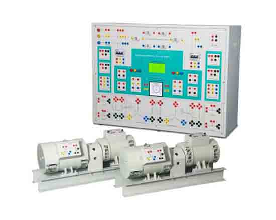
Synchronous Machines are used as Generators in power plants because of their characteristic relation of speed with frequency. The study of power generators is the part of most of the curriculum. 46580 "Synchronous Machine Training System" is an exclusive product designed to demonstrate the fundamental concepts of parallel operation of Three Phase Synchronous Generators. This product is equipped with advanced measurement system for AC Parameters and DC Parameters. It has inbuilt which is highly stable and accurate. Due to use of big size LCD display it is possible to observe mul t iple parameters simultaneously. The RISC microcontroller based design provides better resolution and sensitivity as compared to analog meters. The panel is also equipped with advanced as Phase Sequence Indicator Digital Synchroscope.
Well as Conventional Lamps (Dark Lamp Method) to perform the synchronization of two generators. Students can learn the basics as well as advanced experiments and safety conditions with precautions that are encountered while generating power with multiple generators . Various terminals including three phase starter terminals are provided on front panel to provide flexibility and ease of connections while performing experiments. Students can perform experiments like Synchronization of parallel generators using advanced and conventional methods,behavior of generator, load sharing, power transfer parameters, analysis of voltage regulation of generator, V curve and inverse V curve in Three Phase Synchronous Generators with a vast flexibility.
Features
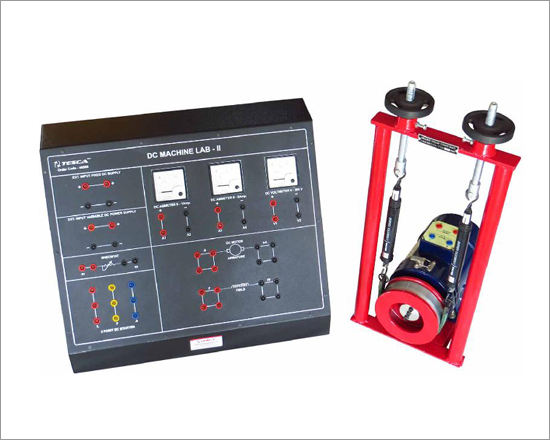
- Two Identical Motor Generator Set
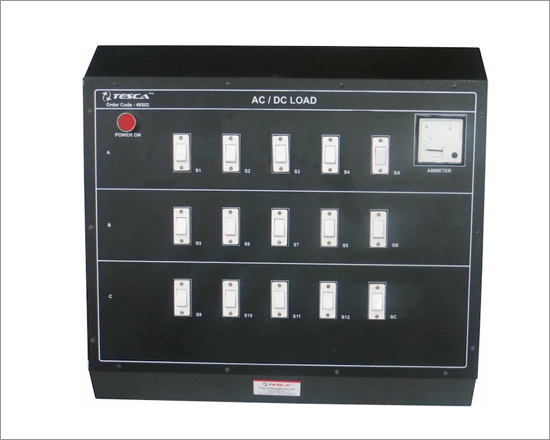
- Electrical Loading Arrangement
- 240 X 128 Graphical LCD Display
- RISC Microcontroller based design for measurement
- High resolution ADC for accurate measurement
- High sensitive to change in reading for better controlling
- Inbuilt Digital Phase Sequence Indicator
- Equipped with Synchroscope
- Inbuilt Multifunction Meter for AC & DC Measurement
- Lamps are provided on front panel for synchronisation
- Designed considering all the safety standards
- Provided with shaft protection cover
- Equipped with supply indication lamps
- Heavy Duty Base/Channel
- Machine with Class "B" Insulation
- Diagrammatic representation for the ease of connections
- Learning material CD
- 2 Year Warranty
Phase Sequence Indicator is unique of its kind. It measures the phase sequence of both the generators individually. When both generators are in same phase then it indicates to proceed further. DC measurement block uses high resolution ADC for voltage measurement and current sensor for DC current measurement. This unit provides accurate voltage & current display with higher resolution.
AC measurement unit acts as multifunction meter to Display Current, Voltage, Frequency, Power & Power Factor. It measures parameters from both the generators.
Scope of Learning
- Synchronization of two Three Phase Alternators by
a) Synchronoscope method
b) Three dark lamp method
c) Two bright one dark lamp method
- Regulation of Three Phase Alternator by
a) Open Circuit test
b) Short Circuit test
- Study & Analysis of V-Curve & Inverse V-Curve of Synchronous Motor
Technical Specifications
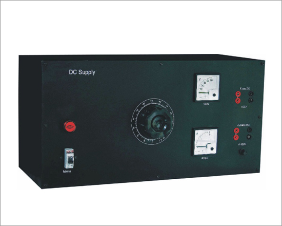
- DC Power Supply
- Input mains : 230V AC ±10%, 50Hz
- Fixed DC output : 200V
- Variable DC output : 0-200V
- AC Measurement Unit
- Voltage : 50 £ 500V
- Current : 0.2 £10A
- Power : 20 £ 2000W
- Power Factor : 0.99 Lead, Lag
- Frequency : 45 £ 55Hz
- DC Measurement Unit
- Voltage : 25 £500V
- Current : 0.2 £10A
- Phase Sequence Indicator : For both generators
- Machines Specification
- Both the M-G Sets are Flexibly Coupled and Mounted on a "C" channel Base
- DC Machine
- Type : Shunt
- Voltage Rating : 200V
- Rating : 2 HP
- Speed : 1500 RPM (no load)
- Insulation : Class "B"
- Three Phase Synchronous Machine
- Type : Salient Pole
- Rating : 3 HP
- Voltage rating : 415V AC
- Speed : 1500 RPM (no load)
- Excitation Voltage : 120V
- Insulation : Class "B"
- Dimensions (mm) : W 930 x D 350 x H 675 (Control Panel)
W 250 x D 900 x H 400 (MG Set)
- Weight : 34kg (approx.) (Control Panel) 212kg (approx.) (MG Set 2 Nos.)
Optional
- DC Power Supply NV725
- Rheostat 2.8A, 220 ohms (4 Nos.)
- Three Phase Resistive Load Nv7067