Educational Equipments Manufacturer, Exporters & Suppliers - School Educational Equipments Manufacturers & Exporters of Educational Equipments for Lab. Science Lab Products, Teaching Aids, Classroom Instruments, Educational Laboratory
UJT Relaxation Oscillator
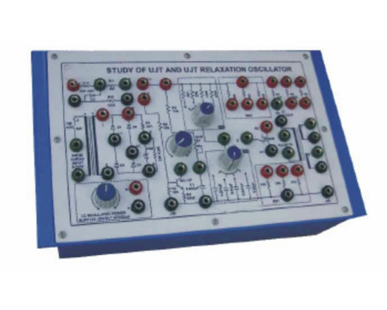
Code:EET3301
Power Electronic Training Board has been designed specifically for the study of Electrical Characteristics of Uni- Junction Transistor. The UJTs are widely used for Relaxation Oscillator, waveform & pulse generators and firing circuits of SCR's and TRIAC's. This Training Board can also make use for designing firing circuits and control circuits for thyristors.Practical experience on this board carries great educative value for Science and Engineering Students.
Object:
- Study of Zener Diode as Voltage Regulator
- Study of Static Emitter Characteristics of UJT- Unijunction Transistor on oscilloscope
- Study of effect of V on peak point and valley point voltage and valley point current. BB
- Operation of UJT Relaxation Oscillator and its use as SCR trigger circuit.
- Control of UJT trigger Pulses with shunt transistor
- Study of Variations in gate resistance & capacitance, resistance of source & drain and their effect on trigger pulse characteristics of UJT relaxation oscillator.
- Various Configurations of UJT relaxation oscillator type 1(low output impedance), type 2 (moderate output impedance) and type 3 (high output impedance)
Features:
The board consists of following built-in parts:
- An isolation transformer 230V A.C. at 100mA. This protects external instruments from damage if they are not isolated.
- 20V D.C. at 100mA, IC Regulated Power Supply internally connected.
- Bridge rectifier and zener regulator
- Potentiometer for frequency control.
- Two band switches for selecting different value of resistance and capacitance.
- Pulse transformer 1:1:1.
- UJT 2N 2646 under experiment
- Adequate no. of other Electronic Components
- Mains ON/OFF switch, Fuse and Jewel light
- The unit is operative on 230V ±10% at 50Hz A.C. Mains.
- Adequate no. of patch cords stackable 4 mm spring loaded plug length ½ metre.
- Good Quality, reliable terminal/sockets are provided at appropriate places on panel for connections/observation of waveforms.
- Strongly supported by detailed Operating Instructions, giving details of Object, Theory, Design procedures, Report Suggestions and Book References.
- Weight : 3 Kg. (Approx.)
- Dimension : W 340 x H 110 x D 210
Other Apparatus Required:
- Digital Multimeter 3¾ digit - Order Code EET3301a
- 0-30V, 1Amp IC Regulated Power Supply
- Dual Trace Cathode Ray Oscilloscope 20 MHz (Unearthed)
- Variac, 0-230VA.C. @ 2Amp
Note: Specifications are subject to change. Order Code can be different from Manufacturer's Model No.
Study of SCR and A.C. Phase Control
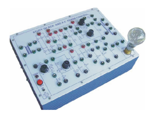
Code:EET3306
Power Electronic Training Board has been designed specifically to study A.C. Phase Control circuits by using different triggering schemes. SCRs are becoming an essential component for power control. Practical experience on this board carries great educative value for Science and Engineering Students.
Object:
To perform the following experiments :
- Resistance trigger circuit for SCR to be operated as half-wave static switch and limited range half wave phase control.
- R.C. trigger circuit for SCR operated as full range half-wave phase control.
- R.C. trigger circuit for SCR connected in bridge full range full-wave phase control.
- Half -wave phase control with SCR using UJT trigger circuit-resistance controlled ramp.
- Full-wave phase control with Inverse Parallel SCRs using UJT trigger circuit-resistance controlled ramp.
- Full-wave phase control with half controlled bridge converter using UJT trigger circuit-resistance controlled ramp.
- UJT trigger circuit with series transistor control ramp.
- UJT trigger circuit using shunt transistor controlled pedestal.
- UJT trigger circuit-resistance controlled pedestal with improved ramp.
- UJT trigger circuit - resistance controlled pedestal with cosine-modified ramp.
Features
The board consists of following built-in parts:
- An isolation transformer 230VA.C. 250mA. This protects external instruments from damage if they are not isolated.
- Bridge rectifier for full-wave phase control with zener regulator.
- Two potentiometers for resistance controlled ramps.
- Two potentiometers for resistance controlled pedestals.
- Uni-Junction Transistor 2N 2646.
- Pulse transformer 1:1:1.
- Three SCRs for half-wave and full-wave inverse parallel connections.
- Adequate no. of other Electronic Components
- Mains ON/OFF switch, Fuse and Jewel light.
- The unit is operative on 230V ±10% at 50Hz A.C. Mains.
- Adequate no. of patch cords stackable 4 mm spring loaded plug length ½ metre.
- Good Quality, reliable terminal/sockets are provided at appropriate places on panel for connections/observation of waveforms.
- Strongly supported by detailed Operating Instructions, giving details of Object, Theory, Design procedures, Report Suggestions and Book References.
- Weight : 7 Kg. (Approx.)
- Dimension : W 412 x H 150 x D 310
Other Apparatus Required:
- Digital Multimeter 3¾ digit - Order Code EET3306a
- 0-30V, 1 Amp IC Regulated Power Supply
Note: Specifications are subject to change. Order Code can be different from Manufacturer's Model No.
DV/DT Limitation of SCR's
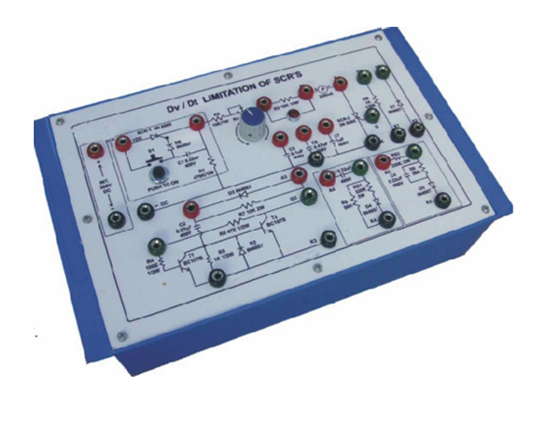
Code:EET3311
Power Electronic Training Board has been designed specifically to study the Dv/Dt characteristics of SCR. It is essential to improve the Dv/Dt capability of SCRs to avoid false firing which may be disastrous in some applications. Different schemes given on the board, help the students to design and study various snubber circuits to improve the Dv/Dt capability of thyristors.Practical experience on this board carries great educative value for Science and Engineering Students.
Object:
To perform the following experiments :
- Test dv/dt estimation of the SCR.
- Compare Dv/Dt capability by Gate-Cathode terminations.
- Compare Dv/Dt capability by Gate-Cathode biasing (Voltage biasing).
- Compare Dv/Dt capability by Gate-Cathode biasing (Current biasing).
- To improve Dv/Dt capability by transistor snubber circuit.
- Effect of R.C. Snubber circuit on Dv/Dt capability.
- Study of different Scheme of R.C. Snubber circuit on Dv/Dt capability.
Features:
The board consists of following built-in parts:
- 300V D.C. at 250 mA, Power Supply internally connected.
- Thyristor switch for applying sudden voltage on the SCR under experiment.
- The SCR under experiment.
- Resistance for gate-cathode termination.
- Silicon diode.
- Transistorized snubber circuit.
- Two schemes for R-C snubber circuits.
- Visual indication to indicate SCR firing.
- Adequate no. of other Electronic Components.
- Mains ON/OFF switch, Fuse and Jewel light.
- The unit is operative on 230V ±10% at 50Hz A.C. Mains.
- Adequate no. of patch cords stackable 4 mm spring loaded plug length ½ metre.
- Good Quality, reliable terminal/sockets are provided at appropriate places on panel for connections/ observation of waveforms.
- Strongly supported by detailed Operating Instructions, giving details of Object, Theory, Design procedures, Report Suggestions and Book References.
- Weight : 3 Kg. (Approx.)
- Dimension : W 340 x H 110 x D 210
Other Apparatus Required:
- Digital Multimeter 3¾ digit - Order Code EET3311
- 0-30V, 1Amp IC Regulated Power Supply
Note: Specifications are subject to change. Order Code can be different from Manufacturer's Model No.
Study of Triac and A.C. Phase Control
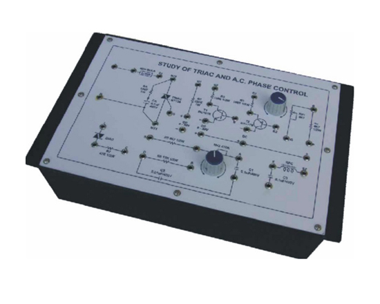
Code:EET3316
Power Electronic Training Board has been designed specifically to study the characteristics of a TRIAC and its application as A.C. Power Control using phase control technique. The unit is provided with built-in load facility. Experiments for the study of radio frequency interference in phase control and methods of their suppression, can be conducted on this training board. Practical experience on this board carries great educative value for Science and Engineering Students.
Object:
To perform the following experiments :
- Study of TRIAC characteristics and its operation in all the four modes i.e. I+, I-, III+ and III-.
- Gate control of TRIAC with NPN transistor.
- Gate control of TRIAC with PNP transistor.
- Phase control with TRIAC and DIAC as pulse generator for gate trigger.
- Light dimmer with TRIAC-hysteresis effect and its minimization by gate slaving technique.
- Study the Radio Frequency Interference (RFI) in phase control and its suppression by RFI filter.
Features:
The board consists of following built-in parts:
- TRIAC.
- DIAC.
- Two potentiometers for biasing and phase control.
- RF choke and capacitor for RFI filter.
- Lamp holder with 40 Watt lamp for load in power control indicator.
- Adequate no. of other Electronic Components.
- Mains ON/OFF switch, Fuse and Jewel light.
- The unit is operative on 230V ±10% at 50Hz A.C. Mains.
- Adequate no. of patch cords stackable 4 mm spring loaded plug length ½ metre.
- Good Quality, reliable terminal/sockets are provided at appropriate places on panel for connections/observation of waveforms.
- Strongly supported by detailed Operating Instructions, giving details of Object, Theory, Design procedures, Report Suggestions and Book References.
- Weight : 3 Kg. (Approx.)
- Dimension : W 340 x H 110 x D 210
Other Apparatus Required:
- Digital Multimeter 3¾ digit - Order Code EET33316a
- 0-30V, 1 Amp IC Regulated Power Supply
- Dual Trace Cathode Ray Oscilloscope 20MHz (Unearthed)
Note: Specifications are subject to change. Order Code can be different from Manufacturer's Model No.
SCR Converters and Reactive Loads
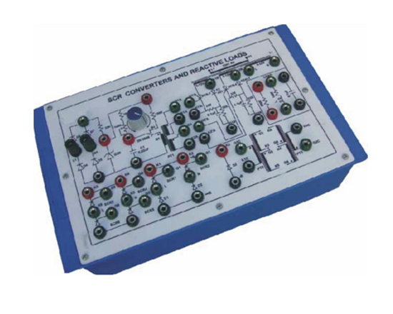
Code:EET3321
Power Electronic Training Board has been designed specifically to study the SCR conduction in different circuit configurations and under various forms of load. The load can be selected from resistive, inductive, capacitive or combinations of any of them. The SCR converter can also be used as source for other experiments. Practical experience on this board carries great educative value for Science and Engineering Students.
Object:
- Study of SCRs triggering in half controlled bridge under reactive loads-limitations of simple UJT triggering circuits.
- Study of SCR triggering in half controlled bridge under reactive loads using auxiliary SCR triggering circuit with extended pulse technique.
- Study of half controlled bridge and action of free wheeling diode.
- Study of fully controlled full wave 4-SCR bridge operation under converter mode.
Features:
The board consists of the following built-in parts :
- UJT relaxation oscillator and triggering pulse generator with resistance ramp control.
- Three numbers of pulse transformers each 1:1:1 type.
- Mains transformer having outputs 0-12V at 100 mA, 0-12V at 100 mA & 0-32V at 500 mA.
- Two SCRs connected in pulse amplifier and extender configuration and used as auxiliary SCR for triggering main SCRs underreactive load.
- Two SCRs and two diodes connected in half-controlled bridge configuration.
- Four SCRs connected in full wave bridge configuration.
- Resistive, Inductive and Capacitive load which can be used individually or in combinations.
- Mains ON/OFF switch, Fuse and Jewel light.
- The unit is operative on 230V ±10% at 50Hz A.C. Mains.
- Adequate no. of patch cords stackable 4 mm spring loaded plug length ½ metre.
- Good Quality, reliable terminal/sockets are provided at appropriate places on panel for connections/observation of waveforms.
- Strongly supported by detailed Operating Instructions, giving details of Object, Theory, Design procedures, Report Suggestions and Book References.
- Weight : 3 Kg. (Approx.)
- Dimension : W 340 x H 110 x D 210
Other Apparatus Required
- Digital Multimeter 3¾ digit - Order Code EET3321a
- Dual Trace Cathode Ray Oscilloscope 20MHz (Unearthed)
Note: Specifications are subject to change. Order Code can be different from Manufacturer's Model No.
SCR Regulated D.C. Power Supply
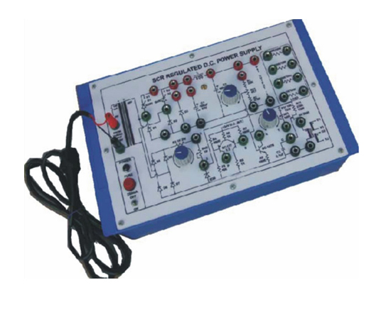
Code:EET3326
Power Electronic Training Board has been designed specifically for the study of continuously variable SCR Regulated Power Supply. The power supply can be manipulated to operate under different circuit conditions in order to provide insight into the important modes of SCR power supply operation. The output voltage can be varied from 10 to 40 Volts continuously. The power supply can also be used as a stabilised source to feed external load up to 500mA. Internal loads are provided to test the performance in 16 steps. Practical experience on this board carries great educative value for Science and Engineering Students.
Object:
- Study of output voltage variation, regulation and ripple in open loop (without feed back) by varying the load using inductance input filter
- Same as above experiment by using capacitor input filter
- Study of output voltage variation, regulation and ripple in closed loop feed back by varying the load using inductance input filtershunt transistor pedestal control.
- Same as above experiment by using capacitor input filter-shunt transistor pedestal control
- Study of variation in output voltage for different slopes of linear resistance controlled ramp.
- Study of line voltage variation (open loop) compensation.
- Study of output voltage variation, regulation and ripple in closed loop feed back by varying load-series transistor controlled ramp in differential amplifier mode
Features:
- 24V D.C. Regulated Power Supply internally connected
- Free wheeling diode
- Transformer 0-40V, 500 mA.
- Two SCRs connected in bridge configuration with rectifiers
- Four diode connected in bridge and one zener for control circuit supply
- UJT 2N 2646 for relaxation oscillator to supply triggering pulses for SCRs
- Pulse transformer 1:1:1.
- Three potentiometers for different modes of voltage adjustment
- Adequate no. of other Electronic Components
- Mains ON/OFF switch, Fuse and Jewel light
- The unit is operative on 230V ±10% at 50Hz A.C. Mains.
- Adequate no. of patch cords stackable 4 mm spring loaded plug length ½ metre.
- Good Quality, reliable terminal/sockets are provided at appropriate places on panel for connections/observation of waveforms
- Strongly supported by detailed Operating Instructions, giving details of Object, Theory, Design procedures, Report Suggestions and Book References
- Weight : 3 Kg. (Approx.)
- Dimension : W 340 x H 110 x D 210
Other Apparatus Required:
- Digital Multimeter 3¾ digit - Order Code EET3326a
- Dual Trace Cathode Ray Oscilloscope 20MHz (Unearthed)
- Variac, 0-230VA.C. @ 2Amp
Note: Specifications are subject to change. Order Code can be different from Manufacturer's Model No.
Triac A.C. Line Switching
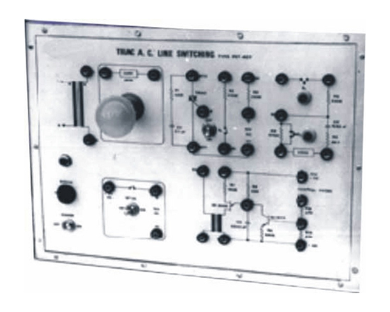
Code:EET3331
Power Electronic Training Board has been designed specifically to study various switching techniques of TRIAC - a bidirectional silicon controlled switch. The phase control applications of TRIAC are included in another board order Code 46521. Practical experience on this board carries great educative value for Science and Engineering Students.
Object:
- Study of TRIAC as line triggered A.C. power switch.
- Study of TRIAC as D.C. triggered A.C. power switch.
- Study of TRIAC as self latching line switch.
- Study of TRIAC as UJT triggered A.C. power switch.
- Study of TRIAC as UJT triggered A.C. power switch with external transistor control from transducer.
Features:
The board consists of the following built in parts:
- An isolation transformer 230VA.C. 250mA. This protects external instruments from damage if they are not isolated.
- 12V D.C. at 250 mA, IC Regulated Power Supply for D.C. Triggering.
- The TRIAC under experiment.
- Two push button switches for triggering.
- UJT 2N 2646 connected in relaxation oscillator mode to provide triggering pulses.
- Pulse transformer 1:1.
- NPN Transistor for UJT control with external transducer.
- Lamp holder with 40 Watt lamp for load in power control indicator.
- Adequate no. of other Electronic Components.
- Mains ON/OFF switch, Fuse and Jewel light.
- The unit is operative on 230V ±10% at 50Hz A.C. Mains.
- Adequate no. of patch cords stackable 4 mm spring loaded plug length ½ metre.
- Good Quality, reliable terminal/sockets are provided at appropriate places on panel for connections/observation of waveforms.
- Strongly supported by detailed Operating Instructions, giving details of Object, Theory, Design procedures, Report Suggestions and Book References.
- Weight : 5 Kg. (Approx.)
- Dimension : W 412 x H 150 x D 310
Other Apparatus Required:
- Digital Multimeter 3¾ digit - Order Code EET3331a
- Dual Trace Cathode Ray Oscilloscope 20MHz (Unearthed)
Note: Specifications are subject to change. Order Code can be different from Manufacturer's Model No.
Thyristor Time Delay Relay
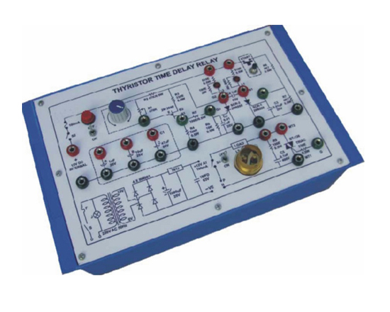
Code:EET3336
Power Electronic Training Board has been designed specifically to study the operation of SCR and TRIAC triggered by electronic time delay circuit. This facilitates to perform the experiment to students both the modes of operation-delayed turn on and auto turn off to control any type of load i.e. A.C. or D.C. Practical experience on this board carries great educative value for Science and Engineering Students.
Object:
- Study of delayed Turn-ON of D.C. load.
- Study of auto Turn-OFF of D.C. load.
- Study of delayed Turn-ON of TRIAC as line switch.
- Study of auto Turn-OFF of TRIAC as line switch.
Features:
The board consists of the following built in parts:
- 12V D.C. at 2 Amp, Power Supply internally connected.
- UJT 2N 2646 used as timer.
- Potentiometer for ramp control to adjust time delay.
- Set of 3 Capacitors for time delay control.
- Two SCRs connected in parallel coupled mode.
- Commutation capacitor.
- Push button switch for starting.
- TRIAC for A.C. line switch.
- Lamp holder with 15 watt 230V lamp for A.C. load.
- Adequate no. of other Electronic Components.
- The unit is operative on 230V ±10% at 50Hz A.C. Mains.
- Adequate no. of patch cords stackable 4 mm spring loaded plug length ½ metre.
- Good Quality, reliable terminal/sockets are provided at appropriate places on panel for connections/observation of waveforms.
- Strongly supported by detailed Operating Instructions, giving details of Object, Theory, Design procedures, Report Suggestions and Book References.
- Weight : 3 Kg. (Approx.)
- Dimension : W 340 x H 110 x D 210
Other Apparatus Required
- Digital Multimeter 3¾ digit - Order Code EET3336a
- Digital Stop Clock
Note: Specifications are subject to change. Order Code can be different from Manufacturer's Model No.
Thyristor Alarms
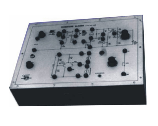
Code:EET3341
Power Electronic Training Board has been designed specifically to study the applications of SCRs in electronic alarm circuits. The high power gain, low leakage currents and high current carrying capacity of SCRs make them ideal for such applications. This training board is an important set up to study various configurations and designs of electronic alarm circuits. The board is absolutely self contained and requires no other apparatus. Practical experience on this board carries great educative value for Science and Engineering Students.
Object
- Study of Make-to-operate alarms.
- Study of Break- to-operate alarms.
- Demonstration of temper-proof burgler alarm.
- Demonstration of alarm with delayed self latching.
- Demonstration of alarm operated with water level.
- Demonstration of alarm sensitive to light beam using L.D.R.
- Demonstration of alarm sensitive to temperature using thermistor.
Features
The board consists of following built-in parts:
- 12V D.C. Power Supply internally connected.
- Internal 12V audio alarm.
- Push button switch for push to break demonstration.
- Push button switch for push to make demonstration.
- One PNP and two NPN transistors for electronic alarm control.
- Two PNP transistors connected in differential amplifier mode for light and temperature sensing.
- SCR for alarm operation.
- Potentiometer for time delay control.
- Potentiometer for balance of differential amplifier.
- ON/OFF switch for 12V D.C. stand by and reset.
- LDR for light sensing and thermistor for temperature sensing.
- Fuse protection for 12V D.C. supply.
- Adequate no. of other Electronic Components.
- Mains ON/OFF switch, Fuse and Jewel light.
- The unit is operative on 230V ±10% at 50Hz A.C. Mains.
- Adequate no. of patch cords stackable 4 mm spring loaded plug length ½ metre.
- Good Quality, reliable terminal/sockets are provided at appropriate places on panel for connections/observation of waveforms.
- Strongly supported by detailed Operating Instructions, giving details of Object, Theory, Design procedures, Report Suggestions and Book References.
- Weight : 3 Kg. (Approx.)
- Dimension : W 340 x H 110 x D 210
Note: Specifications are subject to change. Order Code can be different from Manufacturer's Model No.
SCR Ring Counter
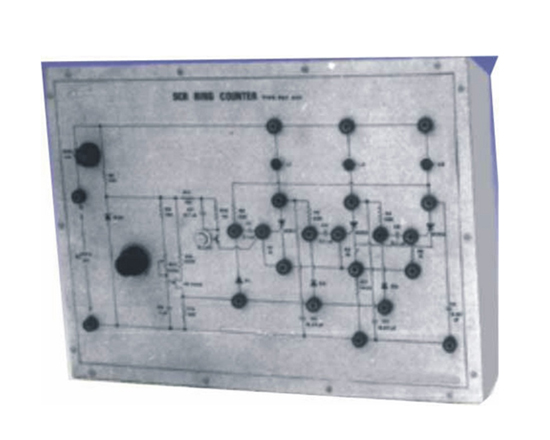
Code:EET3346
Power Electronic Training Board has been designed specifically to study three stage SCR Ring Counter which can be extended to any number of stages by adding identical circuitry, if required. This board demonstrates high power load switching in a sequential order. This set-up can also be used as sequential flash over. The time delay between each sequence is adjustable. This training board facilitates students to understand UJT triggering circuit for SCRs and communication circuit for turning them off in sequential operations. Practical experience on this board carries great educative value for Science and Engineering Students.
Object:
- To study operation of Ring Counter with internal load.
- To study operation of Ring Counter with external load.
Features
The board consists of the following built in parts:
- 20V D.C. Zener Regulated Power Supply for control pulse generator.
- UJT 2N 2646 in relaxation oscillator configuration which provides triggering pulses to SCRs.
- Potentiometer for variable time delay.
- Three SCRs to form three stages of ring counter.
- Three diodes for providing triggering pulses.
- Three dual indicating lamps for indication of sequences.
- UJT 2N 2646 under experiment.
- Adequate no. of other Electronic Components.
- Fuse for protection.
- The unit is operative on 220V D.C. Source.
- Adequate no. of patch cords stackable 4 mm spring loaded plug length ½ metre.
- Good Quality, reliable terminal/sockets are provided at appropriate places on panel for connections/observation of waveforms.
- Strongly supported by detailed Operating Instructions, giving details of Object, Theory, Design procedures, Report Suggestions and Book References.
- Weight : 4 Kg. (Approx.)
- Dimension : W 412 x H 150 x D 310
Other Apparatus Required:
- 220V D.C. at 100mA IC Regulated Power Supply
Note: Specifications are subject to change. Order Code can be different from Manufacturer's Model No.
SCR Triggering Circuit Using IC TCA-785
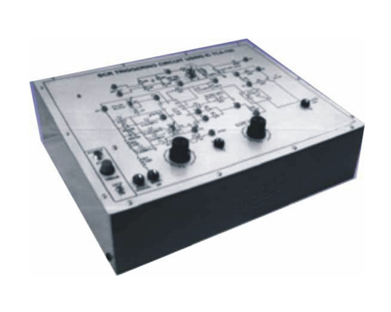
Code:EET3351
Power Electronic Training Board has been designed specifically for the study of SCR Triggering using IC TCA-785. This Training Board gives a better understanding on the operation of Signal Conditioner and Pulse Generator IC TCA-785. Practical experience on this board carries great educative value for Science and Engineering Students.
Object:
To perform the following experiments :
- SCR triggering with controlled gate pulses.
- Change of firing angle in response to the change in reference voltage
- Functioning of Signal Conditioner and Pulse Generator IC TCA-785.
Features:
The board consists of the following built in parts:
- + 15V, +10V D.C. at 50mA, IC Regulated Power Supply internally connected.
- + 5V D.C. at 50mA, IC Regulated Power Supply Isolated.
- Synchronising Signal.
- 24V at 300mAA.C. supply.
- Signal Conditioner and Pulse Generator IC TCA-785.
- Op to Coupler.
- SCR 100V/1Amp.
- Transistor BC-107.
- Adequate no. of other Electronic Components.
- Mains ON/OFF switch, Fuse and Jewel light.
- The unit is operative on 230V ±10% at 50Hz A.C. Mains.
- Adequate no. of patch cords stackable 4 mm spring loaded plug length ½ metre.
- Good Quality, reliable terminal/sockets are provided at appropriate places on panel for connections/observation of waveforms.
- Strongly supported by detailed Operating Instructions, giving details of Object, Theory, Design procedures, Report Suggestions and Book References.
- Weight : 4 Kg. (Approx.)
- Dimension : W 412 x H 150 x D 310
Other Apparatus Required:
- Dual Trace Cathode Ray Oscilloscope 20MHz (Unearthed)
- Bulb 24V/7W
Note: Specifications are subject to change. Order Code can be different from Manufacturer's Model No.
Universal Motor Speed Control
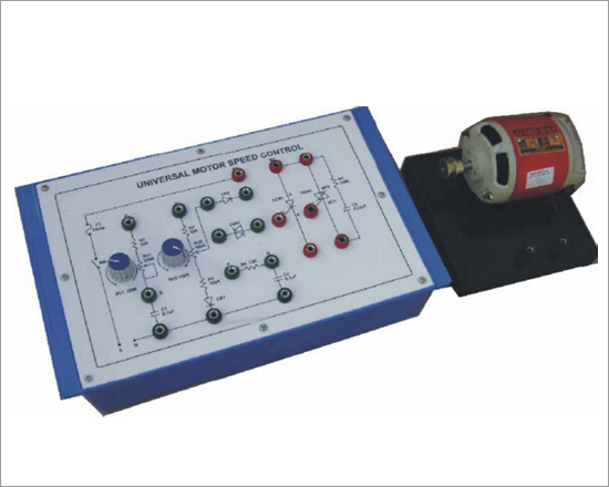
Code:EET3356
Power Electronic Training Board has been designed specifically for the study of speed control of universal motors in different modes, such universal motors are series wound motors capable of operating on both A.C. and D.C. supply. This Training Board is capable of controlling the speed of universal motor up to 1/4th H.P. Capacity.
Practical experience on this board carries great educative value for Science and Engineering Students.
Object:
To perform the following experiments :
- Half wave controller without feed back
- Half wave controller with feed back
- Half wave controller high torque at low speed version - skip cycling operation
- Full wave controller using triac and demonstrating hysteresis effects improved by gate slaving techniques
Features:
The board consists of following built-in parts:
- SCR and TRIAC for the speed control of the universal motor.
- Two potentiometers.
- Two capacitors to control firing angle of thyristors.
- DIAC and two Nos. of diodes.
- A Universal motor of 1/12 H.P. or less capacity.
- Snubber circuit in parallel with the triac, which helps in improving the Dv/Dt of the device and also helps in reducing the RFI.
- Adequate no. of other Electronic Components.
- Mains ON/OFF switch, Fuse and Jewel light.
- The unit is operative on 230V ±10% at 50Hz A.C. Mains
- Adequate no. of patch cords stackable 4 mm spring loaded plug length ½ metre
- Good Quality, reliable terminal/sockets are provided at appropriate places on panel for connections/ observation of waveforms
- Strongly supported by detailed Operating Instructions, giving details of Object, Theory, Design procedures, Report Suggestions and Book References
- Weight : 3 Kg. (Approx.)
- Dimension : W 340 x H 110 x D 210
Other Apparatus Required
- Digital Multimeter 3¾ digit - Order Code EET3356a
- Dual Trace Cathode Ray Oscilloscope 20MHz (Unearthed)
Note: Specifications are subject to change. Order Code can be different from Manufacturer's Model No.
To Trigger a SCR by Using a LDR
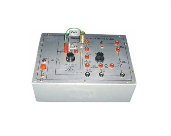
Code:EET3361
Power Electronic Training Board has been designed specifically to study trigger of a SCR by using a LDR. Practical experience on this board carries great educative value for Science and Engineering Students.
Object:
- To trigger a SCR by using a LDR.
Features:
The board consists of the following built in parts :
- 6VA.C. at 2 Amp power supply internally connected
- SCR.
- LDR mounted on Panel
- Two potentiometers for intensity and sensitivity control.
- Adequate no. of other electronic components.
- Mains ON/OFF switch, Fuse and Jewel light.
- The unit is operative on 230V ±10% at 50Hz A.C. Mains
- Good Quality, reliable terminal/sockets are provided at appropriate places on panel for connections / observation of waveforms.
- Strongly supported by detailed Operating Instructions, giving details of Object, Theory, Design procedures, Report Suggestions and Book References.
- Weight : 3 Kg. (Approx.)
- Dimension : W 340 x H 110 x D 210
Other Apparatus Required:
- Digital Multimeter 3¾ digit - Order Code EET3361a
- Cathode Ray Oscilloscope 20MHz
Note: Specifications are subject to change. Order Code can be different from Manufacturer's Model No.
Single Phase Fully- Controlled Bridge Converter
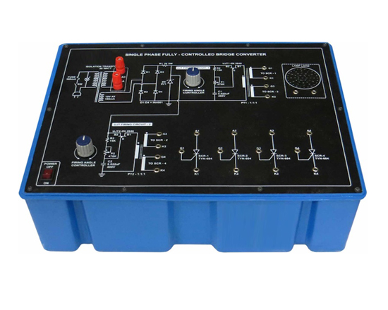
Code:EET3366
Power Electronic Training Board has been designed specifically to study and obtain the single phase fully controlled bridge converter. Practical experience on this board carries great educative value for Science and Engineering Students.
Object:
- To study and obtain the single phase fully controlled bridge converter.
Features:
The board consists of the following built-in parts:
- 230VA.C. Isolated Transformer, Power 50 watt.
- 9V D.C. at 100mA Zener Regulated Power Supply.
- Two UJT.
- Four SCR's.
- Two Pulse transformer 1:1:1.
- Two Potentiometers for controlling UJT firing angle.
- Bulb 40W, 230VA.C.
- Adequate no. of other Electronic Components.
- Mains ON/OFF switch, Fuse and Jewel light.
- The unit is operative on 230V ±10% at 50Hz A.C. Mains.
- Adequate no. of patch cords stackable 4 mm spring loaded plug length ½ metre.
- Good Quality, reliable terminal/sockets are provided at appropriate places on panel for connections/observation of waveforms.
- Weight : 6 Kg. (Approx.)
- Dimension : W 300 x H 140 x D 200
Other Apparatus Required:
- Dual Trace Cathode Ray Oscilloscope 20 MHz (Unearthed)/with Isolation Transformer for unearthing.
Note: Specifications are subject to change. Order Code can be different from Manufacturer's Model No.
SCR D.C. Circuit Breaker
Code:EET3371
Power Electronic Training Board has been designed specifically to study the SCR as D.C. circuit breaker when the D.C. circuit exceeds specified limit. The set up works on 30V D.C. and permits the circuit breaker to be adjusted from 100mA to 1.8 Amp. This Training Board also includes Electronic Crow Bar circuitry to demonstrate the over voltage and over current trip under D.C. Condition. Practical experience on this board carries great educative value for Science and Engineering Students.
Object:
- To study SCR turn OFF action under varying loads.
- To study D.C. over voltage trip action.
- To study over current trip action.
Features
The board consists of the following built-in parts:
- 20V D.C. Zener Stabilized Power Supply for UJTs.
- Two SCRs, one main and one auxiliary.
- Two push button switches, one to trigger the main SCR and other to trigger the auxiliary SCR which turns the main SCR OFF.
- Two UJTs connected in relaxation oscillator mode.
- Two potentiometers to adjust the over voltage and over current limit.
- Capacitor bank to study commutation under different load.
- Resistance bank for varying load.
- Adequate no. Of other Electronic Components.
- Fuse protection in D.C. supply.
- The unit is operative on 30V D.C. at 2 Amp.
- Adequate no. of patch cords stackable 4 mm spring loaded plug length ½ metre.
- Good Quality, reliable terminal/sockets are provided at appropriate places on panel for connections/observation of wave forms.
- Strongly supported by detailed Operating Instructions, giving details of Object, Theory, Design procedures, Report Suggestions and Book References.
- Weight : 4 Kg. (Approx.)
- Dimension : W 412 x H 150 x D 310
Other Apparatus Required:
- Digital Multimeter 3¾ digit - Order Code EET3371a
- 0-30V D.C.-2 Amp, IC Regulated Power Supply
- Dual Trace Cathode Ray Oscilloscope 20MHz (Unearthed)
Note: Specifications are subject to change. Order Code can be different from Manufacturer's Model No.
SCR Lamp Flasher
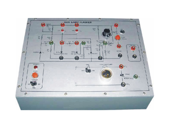
Code:EET3376
Power Electronic Training Board has been designed specifically to study the use of SCR and TRIAC in D.C. and A.C. lamp flasher respecively. The flasher is useful for students of understand the application of SCRs in D.C. flasher, triggered by UJT relaxation oscillator. The repetition rate of the flasher can be varied by varying the frequency of the relaxation oscillator. This Training Board also makes use of the same SCR D.C. flasher for making the TRIAC ON and OFF in the A.C. power circuit which operates a normal 230V incandescent lamp used as load. Practical experience on this board carries great educative value for Science and Engineering Students.
Object:
To perform the following experiments :
- Symmetrical D.C. flasher.
- High power A.C. flasher.
Features:
The board consists of the following built-in parts:
- 12V D.C. at 100mA, IC Regulated Power Supply.
- Two SCRs.
- TRIAC 4 Amp./400PIV
- 230V/40 Watt lamp for load.
- UJT 2N 2646 in relaxation oscillator mode.
- Two LEDs to demonstrate Twin-lamp D.C. flasher.
- Potentiometer for frequency variation.
- Two numbers of toggle switches, one for D.C. flasher, and one for A.C. flasher.
- Adequate no. of other Electronic Components.
- Mains ON/OFF switch, Fuse and Jewel light.
- The unit is operative on 230V ±10% at 50Hz A.C. Mains.
- Adequate no. of patch cords stackable 4 mm spring loaded plug length ½ metre.
- Good Quality, reliable terminal/sockets are provided at appropriate places on panel for connections/ observation of waveforms.
- Strongly supported by detailed Operating Instructions, giving details of Object, Theory, Design procedures, Report Suggestions and Book References.
- Weight : 5 Kg. (Approx.)
- Dimension : W 412 x H 150 x D 310
Other Apparatus Required:
- Digital Multimeter 3¾ digit - Order Code EET376a
- Dual Trace Cathode Ray Oscilloscope 20MHz (Unearthed)
Note: Specifications are subject to change. Order Code can be different from Manufacturer's Model No.
Triggering Circuits for SCR
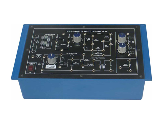
Code:EET3381
Power Electronic Training Board has been designed specifically for the study of SCR Triggering circuits. Practical experience on this board carries great educative value for Science and Engineering Students.
Object:
To study the SCR Triggering circuits using
- Resistor (R) Triggering circuit
- Resistor - capacitor (R-C) Triggering circuit
- Uni-junction Transistor (UJT) Triggering circuit (UJT relaxation Oscillator)
- Half-wave controlled rectifier
- Full-wave controlled rectifier.
Features:
The board consists of the following built-in parts:
- 35VA.C. at 100mAA.C. Power Supply.
- Bridge rectifier for making D.C. voltage.
- Two Silicon controlled rectifier (SCR).
- Uni junction Transistor.
- Pulse transformer 1:1.
- Two potentiometer for varying load.
- Two potentiometer one for controlling SCR firing angle and other for controlling UJT firing angle.
- Adequate no. of other Electronic Components.
- Mains ON/OFF switch, Fuse and Jewel light.
- The unit is operative on 230V ±10% at 50Hz A.C. Mains.
- Adequate no. of patch cords stackable 4 mm spring loaded plug length ½ metre.
- Good Quality, reliable terminal/sockets are provided at appropriate places on panel for connections/ observation of waveforms.
- Strongly supported by detailed Operating Instructions, giving details of Object, Theory, Design procedures, Report Suggestions and Book References.
- Weight : 3 Kg. (Approx.)
- Dimension : W 340 x H 110 x D 210
Other Apparatus Required
- Dual Trace Cathode Ray Oscilloscope 20MHz (Unearthed)
Note: Specifications are subject to change. Order Code can be different from Manufacturer's Model No.
Single Phase HalfWave Controlled Converter

Code:EET3386
Power Electronic Training Board has been designed specifically stydy of single phase half wave controlled converter. Practical experience on this board carries great educative value for Science and Engineering Students.
Object:
- Study and obtain the waveforms for single-phase half wave controlled converter.
Features:
The board consists of the following built-in parts :
- 230VA.C. Isolated Transformer, Power 50 watt.
- 9V D.C. at 100mA Zener Regulated Power Supply.
- Silicon Controlled Rectifier (SCR).
- Uni Junction Transistor.
- Pulse transformer 1:1.
- Potentiometer for controlling UJT firing angle.
- Bulb 40W, 230VA.C.
- Adequate no. of other Electronic Components.
- Mains ON/OFF switch, Fuse and Jewel light.
- The unit is operative on 230V ±10% at 50Hz A.C. Mains.
- Adequate no. of patch cords stackable 4 mm spring loaded plug length ½ metre.
- Good Quality, reliable terminal/sockets are provided at appropriate places on panel for connections/ observation of waveforms.
- Strongly supported by detailed Operating Instructions, giving details of Object, Theory, Design procedures, Report Suggestions and Book References.
- Weight : 6 Kg. (Approx.)
- Dimension : W 300 x H 140 x D 200
Other Apparatus Required:
- Dual Trace Cathode Ray Oscilloscope 20MHz (Unearthed)/with Isolation Transformer for unearthing
Note: Specifications are subject to change. Order Code can be different from Manufacturer's Model No.
Single Phase Half Controlled Symmetrical &Asymmetrical Bridge Converter
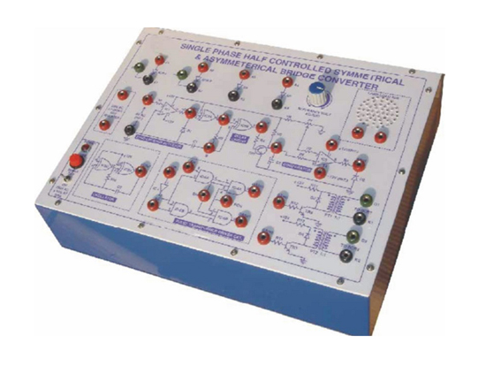
Code:EET3391
Power Electronic Training Board has been designed specifically to study and obtain the waveforms for single phase half controlled symmetrical & asymmetrical bridge converter.Practical experience on this board carries great educative value for Science and Engineering Students.
Object
- To study and obtain the single phase half controlled symmetrical bridge converter.
- To study and obtain the single phase half controlled asymmetrical bridge converter.
Features
The board consists of the following built-in parts:
- An isolation transformer 230VA.C. at 200mA. This protects external instruments for damage if they are not isolated.
- 6VAC at 100mAAC Power Supply.
- ±12V DC at 100mA fixed regulated Power Supply.
- Two Op-Amp's. IC.
- Quad, Ex-OR gate IC.
- Triple, 3 input AND gate IC.
- Hex inverter gate IC.
- Quad, two input AND gate IC.
- Three NPN Transistor.
- Two SCR's.
- Potentiometer for referance voltage adjustment.
- Two Pulse Transformer 1: 1.
- 40 watt bulb.
- Adequate no. of other Electronic Components.
- Mains ON/OFF switch, Fuse and Jewel light.
- The unit is operative on 230V ±10% at 50Hz A.C. Mains.
- Adequate no. of patch cords stackable 4 mm spring loaded plug length ½ metre.
- Good Quality, reliable terminal/sock ets are provided at appropriate places on panel for connections/observation of waveforms.
- Strongly supported by detailed Operating Instructions, giving details of Object, Theory, Design procedures, Report Suggestions and Book References.
- Weight : 7 Kg. (Approx.)
- Dimension : W 412 x H 150 x D 310
Other Apparatus Required
- Dual Trace Cathode Ray Oscilloscope 20MHz (Unearthed
Note: Specifications are subject to change. Order Code can be different from Manufacturer's Model No.
AC Regulators Using Triac, Anti Parallel Thyristor and Triac & Diac
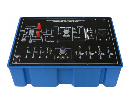
Code:EET3396
Power Electronic Training Board has been designed specifically for to study A.C. Regulators using triac, antiparallel thyristor and triac & diac.Practical experience on this board carries great educative value for Science and Engineering Students.
Object
- A.C. Regulator using a Triac.
- A.C. Regulator using Thyristor connected in antiparallel.
- A.C. Regulator using a triac & a diac (with R.C. triggering circuit).
Features
The board consists of the following built-in parts :
- 230VA.C. Isolated Transformer, Power 50 Watt.
- 9V D.C. at 100mA Zener Regulated Power Supply.
- Two silicon controlled rectifiers (SCR's).
- Uni Junction Transistor (UJT).
- TRIAC.
- DIAC.
- Pulse Transformer 1:1:1.
- Two potentiometers one for controlling UJT firing angle & other for varying load.
- Bulb 40W, 230VA.C.
- Mains ON/OFF switch, Fuse and Jewel light.
- The unit is operative on 230V ±10% at 50Hz A.C. Mains.
- Adequate no. of patch cords stackable 4 mm spring loaded plug length ½ metre.
- Good Quality, reliable terminal/sockets are provided at appropriate places on panel for connections/ observation of waveforms.
- Strongly supported by detailed Operating Instructions, giving details of Object, Theory, Design procedures, Report Suggestions and Book References.
- Weight : 6 Kg. (Approx.)
- Dimension : W 300 x H 140 x D 200
Other Apparatus Required
- Dual Trace Cathode Ray Oscilloscope 20MHz (Unearthed)/with isolation transformer for unearthing.
Note: Specifications are subject to change. Order Code can be different from Manufacturer's Model No.


