Educational Equipments Manufacturer, Exporters & Suppliers - School Educational Equipments Manufacturers & Exporters of Educational Equipments for Lab. Science Lab Products, Teaching Aids, Classroom Instruments, Educational Laboratory
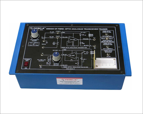
Fibre-Optic Simplex Analogue Transceiver Trainer

Code:EET2641
Fibre-Optic Simplex Analogue Transceiver Trainer has been designed specifically for the study of a typical linear intensity modulation system for analogue signal transmission. Practical experience on this board carries great educative value for Science & Engineering Students.
Object
- Gain characteristics of a fibre optic Linear Intensity Modulation System Vin (ac) Vs Vo (ac) for fixed carrier power Po and signal frequency
- Frequency Response of ac fibre-Optic Linear Intensity Modulation System. Vout (ac) Vs fo at fixed carrier power Po and Vin (ac).
- Gain-Band width Product of a fibre Optic Linear Intensity Modulation Receiver. Gain Vs Bandwidth for fixed Vin.
Features:
The board consists of the following built-in parts::
- IC Regulated D.C. Power Supply.
- Fibre-Optic Transmitter
- Fibre-Optic Receiver
- Potentiometer to vary the current of LED in Transmitter and Photo transistor in receiver.
- Adequate no of other electronic componets.
- Mains ON/OFF switch, Fuse and Jewel light.
- The unit is operative on 230V ±10% at 50Hz A.C. Mains.
- Adequate no. of patch cords stackable 4mm spring loaded plug length ½ metre.
- Good Quality, reliable terminal/sockets are provided at appropriate places on panel for connections / observation of waveforms.
- Strongly supported by detailed Operating Instructions, giving details of Object, Theory, Design procedures, Report Suggestions and Book References.
- Weight : 3 Kg. (Approx)
- Dimension : W 340 x H 110 x D 210
Other Apparatus Required:
- AF/RF Generator 10Hz to 1MHz Order Code - EET2641a
- Digital Multimeter Order Code - EET2641b
- Cathode Ray Oscilloscope 20MHz
Fibre-Optic Simplex Digital Transceiver Trainer
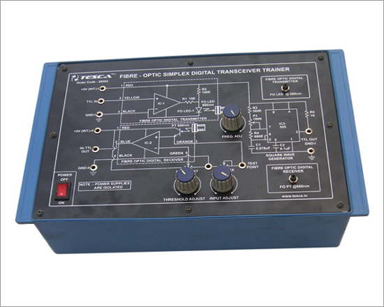
Code:EET2646
Fibre-Optic Simplex Digital Transceiver Trainer has been designed specifically for the study of characteristics & propagation delay in digital fibre optic transmission systems.
Practical experience on this board carries great educative value for science & engineering students.
Object
- Design & study of a fibre-optic Digital link.
- Study of Rise-Time and Fall-Time distortions
- Study of Propagation Delay.
Features:
The board consists of the following built-in parts::
- Two isolated IC Regulated D.C. Power Suppliers.
- Timer IC for Square Wave Frequency Generator.
- Three potentiometers to vary R (Threshold Resistance), R (Input Resistance) and frequency. TH IN
- Fibre Optic Digital Transmitter @ 660nm
- Fibre Optic Digital Receiver.
- Adequate no of other electronic componets.
- Mains ON/OFF switch, Fuse and Jewel light.
- The unit is operative on 230V ±10% at 50Hz A.C. Mains.
- Adequate no. of patch cords stackable 4mm spring loaded plug length ½ metre.
- Good Quality, reliable terminal/sockets are provided at appropriate places on panel for connections / observation of waveforms.
- Strongly supported by detailed Operating Instructions, giving details of Object, Theory, Design procedures, Report Suggestions and Book References.
Other Apparatus Required:
- Digital Multimeter Order Code - EET2646a
- Cathode Ray Oscilloscope 20MHz
Advanced Fibre-Optic Analogue Transceiver Trainer
Code:EET2651
Fibre-Optic Simplex Analogue Transceiver Trainer has been designed specifically for the study of a typical linear intensity modulation system for analogue signal transmission. Practical experience on this Trainer carries great educative value for Science & Engineering Students.
Object
- To determine the Numerical Aperature of optical fibre.
- Losses in Optical Fibres at 660nm and 850nm and other cables.
- Study of E/O Characteristic of Fibre Optic 660nm and 850nm.
- Study of O/E Characteristic of Fibre Optic photo transistor.
- Design and study of a linear Fibre Optic Intensity Modulation system for analog transmission :
- Gain characteristics of a Fibre Optic Linear Intensity Modulation System.
- Frequency Response of a Fibre Optic Linear Intensity Modulation System.
- Waveform distortion in a Fibre Optic Linear Intensity Modulation System.
- Gain-Band width product of a fibre optic linear intensity Modulation System.
Features:
The board consists of the following built-in parts::
- IC regulated D.C. power supply.
- Fibre-Optic Analogue Transmitter @ 660nm
- Fibre-Optic Analogue Transmitter @ 850nm
- Fibre-Optic Receiver.
- One-metre PMMA Fibre patch cord.
- Five-metre PMMA Fibre patch cord.
- In-line SMA adaptor.
- Two potentiometer to vary forward current of LED in Transmitter & current of photo transistor in receiver.
- SPDT switch for selecting wavelengths 660nm and 850nm.
- NA JIG with scale marked on it to measure length.
- Mandrel.
- NA measuring Scale to measure width of Fibre Optic's LED.
- Adequate no of other electronic componets.
- Mains ON/OFF switch, Fuse and Jewel light.
- The unit is operative on 230V ±10% at 50Hz A.C. Mains.
- Adequate no. of patch cords stackable 4mm spring loaded plug length ½ metre.
- Good Quality, reliable terminal/sockets are provided at appropriate places on panel for connections / observation of waveforms.
- Strongly supported by detailed Operating Instructions, giving details of Object, Theory, Design procedures, Report Suggestions and Book References.
- Weight : 3 Kg. (Approx)
- Dimension : W 340 x H 110 x D 210
Other Apparatus Required:
- AF/RF Generator 10Hz to 1MHz Order Code - EET2651a
- Digital Fibre-Optic Power meter Order Code - EET2651b
- Digital Multimeter Order Code - EET2646c
- Cathode Ray Oscilloscope 20MHz
Advanced Fibre-Optic Digital Transceiver Trainer
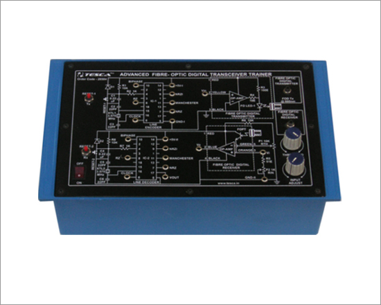
Code:EET2656
Fibre-Optic Digital Transceiver Trainer has been designed specifically for the study of encoding methods used in digital fibre Optic. transmission system.
Practical experience on this board carries great educative value for Science & Engineering Students.
Object
- Design and study of a Fibre-optic digital link
- Study of rise-time and fall-time distortions
- Study of propagation delay.
- Encoding methods for fibre-optic digital transmission
- Base band or Non Return to Zero (NRZ) Transmission
- Return to Zero coding (RZ)
- Non Return to zero inverted coding (NRZI)
- Biphase Coding
- Manchester Coding.
Features:
The board consists of the following built-in parts::
- Fibre-Optic digital transmitter @ 660nm
- Fibre-Optic digital receiver
- Two Potentiomet
- Two Isolated IC regulated D.C. power supplies
- ers to vary, RIN (input resistance) of receiver and RTH (Threshold resistance) of receiver.
- Encoder IC
- Decoder IC
- Two Crystals
- Two reset switches resetting encoder and decoder
- Adequate no of other electronic componets.
- Mains ON/OFF switch, Fuse and Jewel light.
- The unit is operative on 230V ±10% at 50Hz A.C. Mains.
- Adequate no. of patch cords stackable 4mm spring loaded plug length ½ metre.
- Good Quality, reliable terminal/sockets are provided at appropriate places on panel for connections / observation of waveforms.
- Strongly supported by detailed Operating Instructions, giving details of Object, Theory, Design procedures, Report Suggestions and Book References.
- Weight : 3 Kg. (Approx)
- Dimension : W 340 x H 110 x D 210
Other Apparatus Required:
- Cathode Ray Oscilloscope 20MHz
Fibre-Optic Trainer for Numerical Aperature and Fibre Loss Measurement
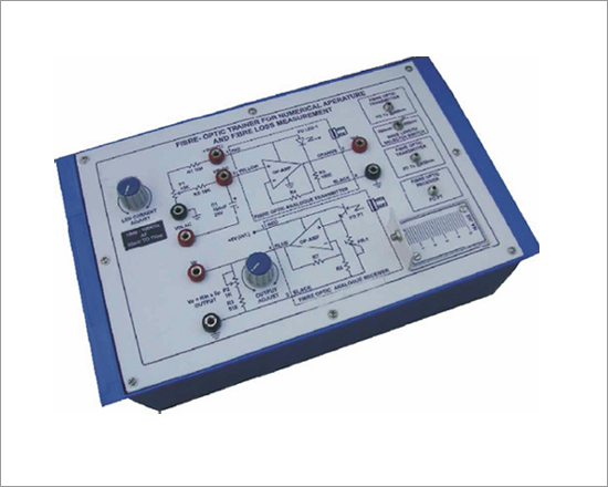
Code:EET2661
Fibre-OpticTrainer for Numerical Aperature and Fibre Loss Measurement has been designed specifically for the study of Numerical Aperature and Fibre Loss Measurement. Practical experience on this Trainer carries great educative value for Science & Engineering Students.
Object:
- Fibre Optic Transmitter and Receiver
- Numerical Aperture of PMMA Fibre .
- Loss in 1 Mtr / 5 Mtr. PMMA Patch Chords.
- Electrical - Optical Converter Characteristics.
- Optical to Electrical Converter Characteristics.
- Intensity Modulation System.
Features:
The Trainer consists of the following built-in parts:
- IC regulated D.C. Power Supply.
- Fibre-Optic Analogue Transmitter @ 660 nm
- Fibre-Optic Analogue Transmitter @ 850 nm
- Fibre-Optic Receiver.
- One-metre PMMA Fibre Patch cord.
- Five-metre PMMA Fibre Patch cord.
- In-line SMA Adaptor.
- Two Potentiometer to vary forward current of LED in Transmitter & current of Phototransistor in receiver.
- SPDT switch for selecting wavelengths 660 nm and 850 nm.
- NA JIG with scale marked on it to measure length.
- Mandrel.
- NA measuring Scale to measure width of Fibre Optic's LED.
- Adequate no of other electronic componets.
- Mains ON/OFF switch, Fuse and Jewel light.
- The unit is operative on 230V ±10% at 50Hz A.C. Mains.
- Adequate no. of patch cords stackable 4mm spring loaded plug length ½ metre.
- Good Quality, reliable terminal/sockets are provided at appropriate places on panel for connections / observation of waveforms.
- Strongly supported by detailed Operating Instructions, giving details of Object, Theory, Design procedures, Report Suggestions and Book References.
- Weight : 3 Kg. (Approx)
- Dimension : W 340 x H 110 x D 210
Other Apparatus Required:
- AF/RF Generator 10Hz to 1MHz Order Code - EET2661a
- Digital Fibre-Optic Power meter Order Code - EET2661b
- Digital Multimeter Order Code - EET2661c
- Cathode Ray Oscilloscope 20MHz.
Fibre-Optic Voice Transmitter & Receiver Trainer
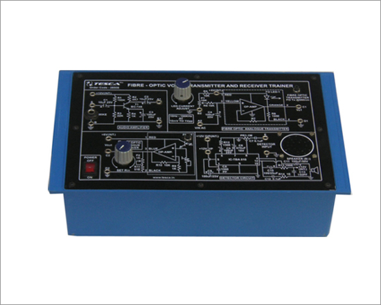
Code:EET2666
Fibre-Optic Voice Transmitter and Receiver Trainer has been designed specifically to learn mysteries and science of Fibre Optics. In a way it is a Lab-Optics Voice Link Trainer. Practical experience on this Trainer carries great educative value for Science & Engineering Students.
Features:
- Study of fibre - optic transmitter and receiver for audio signal transmission.
- Study of fibre - optic transmitter and receiver for voice signal transmission.
Technical Specifications
- Fibre-Optic Transmitter @ 660nm.
- Audio Amplifier Circuit.
- 12V & 6V DC at 200mA, IC Regulated power supply internally connected.
- One mike connector.
- Potentiometer to vary the current of LED.
- Fibre - Optic Photo Transistor.
- Detector Circuit with Speaker of 8 ohms.
- Mains ON/OFF, Fuse and Jewel Light.
- A mike to transmit voice.
- One meter and five-meter PMMA patch cords with in - line adaptor.
- he units are operative on 230V ±10% at 50Hz A.C. Mains.
- Adequate no. of Patchcords stackable 4mm spring loaded plug length ½ metre.
- Good Quality, reliable Terminal/Sockets are provided at appropriate places on Panel for connections / observation of waveforms.
- Strongly supported by detailed Operating Instructions, giving details of Object, Theory, Design procedures, Report Suggestions and Book References.
- Weight : 3 Kg. (Approx)
- Dimension : W 340 x H 110 x D 210
Other Apparatus Required:
- Cathode Ray Oscilloscope 20MHz.
- AF/RF Generator 10Hz to 1 MHz Order Code - EET2666a
Laser Diode Intensity Modulation and Demodulation Trainer
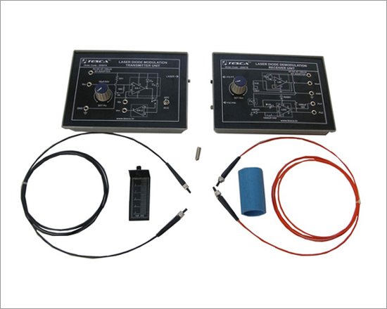
Code:EET2671
Laser Diode Intensity Modulation and Demodulation Trainer has been developed to conduct studies on laser Diode, optical fibres and optical communication methods, by signal transmission.
Practical experience on this Trainer carries great educative value for Science & Engineering Students.
Experiments:
- Characterisation of a Laser Diode.
- Optical Power (Po) of a Laser Diode Vs Laser Diode Forward current (I ). F
- Monitor Photodiode Current (I ) Vs Laser Optical Power Output (Po). M
- Study of Automatic Current Control (ACC) or Automatic Power Control (APC) Modes of Operation
- Comparison of ACC and APC Modes of Operation.
- Design and Evaluation of an Laser Diode (LD) Analog I System M
- Vo Vs Vin at Specified Optical Carrier Power Levels, Po.
- Determination of Vin (max) at Specified Po for Distortion-free Vo.
- Design and Evaluation of Laser Diode LD Digital Transmission System
- Risetime and Falltime Pulsewidth Distortions and Determination of Propogation Delay.
- Transmission of Laser through an Optical Fibre
- To measure loss in dB of Step-index Multimode plastic Fibre Patchcord.
- To measure loss in dB of Graded-Index, Multimode Glass Fibre Patchcord.
- To measure loss in dB of Two Patchcords connected by the in-line Adaptor.
- Laser Free Space Communication
- Analogue Free Space Communication System.
- Digital Free Space Communication System
- Determination of Numerical Aperature of PMMA Fibre Cable
Technical Specifications
- Laser Diode Transmitter unit having following built-in parts :
- Laser Diode Transmitter Module.
- 6V DC at 100mA, IC Regulated Power Supply internally connected.
- SPDT switch to select Automatic Current Control (ACC) or Automatic Power Control (APC).
- Potentiometer to set power output.
- Adequate no.of other electronic components.
- Mains ON/OFF switch, Fuse and Jewel light.
- Laser Diode Receiver unit having following built-in parts :
- Laser Diode Receiver Module.
- PIN Diode for measuring power of Laser Diode.
- Potentiometer to set voltage output.
- Adequate no.of other Electronic Components.
- 6V DC at 100mA, IC Regulated Power Supply internally connected.
- Two-metres PMMA Plastic Fibre Patchcord (Cable-1).
- Two-metres GI/mm Glass Fibre Patchcord (Cable-2).
- In-line SMA Adaptor.
- Numerical Aperature measurement Jig.
- Mandrel.
- The units are operative on 230V ±10% at 50Hz A.C. Mains.
- Adequate no. of Patch cords stackable 4mm spring loaded plug length ½ metre.
- Good Quality, reliable Terminal/Sockets are provided at appropriate places on panel for connections / observation of waveforms.
- Strongly supported by detailed Operating Instructions, giving details of Object, Theory, Design Procedures, Report Suggestions and Book References.
- Weight : 4 Kg. (Approx)
- Dimension : W 340 x H 110 x D 210
Other Apparatus Required:
- AF/RF Generator 10Hz to 1 MHz Order Code - Code:EET2671a
- Three Digital Multimeter Order Code - EET2671b
- Cathode Ray Oscilloscope 20MHz
Physics of Fiber Optics Trainer
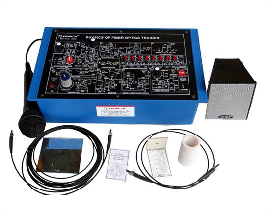
Code:EET2676
PHYSICS OF FIBER OPTICS TRAINER is designed to learn basic physics of fiber optics including fiber end preparation. Students can also study the construction of transmitter & receiver to form analog & digital link. Ample number of experiments can be performed with this kit by referring to the exhaustive manuals provided with the kit.
List of Experiments:
- Light traveling around corners in an Optical Fiber
- Coloured light traveling down an Optical Fiber
- Photo detector detecting light
- LED output as a function of a current
- LED shining light into
- Transmission of light between two fibers
- Transmission through a gap between fibers
- Fiber Optic transmission sensor
- Fiber Optic reflection sensor
- Measuring Losses in the fiber
- Measurement of propagation loss in the Fiber
- Measurement of connector loss
- Fiber bending loss
- Measurement of Numerical Aperture of Optical Fiber
- Setting up of Fiber Optic Analog Link
- Setting up of Fiber Optic Digital Link
- Setting of Fiber Optic Voice Link.
- Switch Faults Study
- Effect of switch fault 1 in function generator section
- Effect of switch fault 2 in audio pre amplifier section
- Effect of switch fault 3 in signal strength section
- Effect of switch fault 4 in audio amplifier section
Features
- On-board Function Generator.
- Transmitter : 1 No.
- Receiver : 2 Nos
- Fiber Optic Analog Link.
- Fiber Optic Digital Link.
- Signal strength indicator.
Technical Specifications
- Transmitter : 1 No. LED. Peak wavelength of emission, 635 nm Red visible.
- Receiver : 2 Nos. silicon photo detectors
- Modulation : Intensity modulation.
- Driver Circuit : Analog and digital configuration for 635 nm LED
- Analog Bandwidth : 35KHz.
- Digital Bandwidth : 50KHz.
- On-Board Function Generator :
- Sine Wave &TTL Square Wave :
- Frequency Range : 1Hz to 10Hz, 10Hz to 100Hz, 100Hz to 1 K H z , 1 K H z t o 10KHz
- Amplitude : 0 to 4Vpp. (Except Square)
- Voice Communication : Fiber Optic voice link using dynamic MIC &SPEAKER
- Signal strength indicator : 8 LED's provided to m e a s u r e o p t i c a l power.
- Fiber Optic Cable :
- Type : 1000 micron Step Index, Multimode Plastic Fiber
- Fiber Lengths : 1&5 Meter.
- Power Supply : GND, +5V, +12V, -12V at100mAINT.
Accessories:
- SRed Short Links : 10 Nos.
- Crocodile Links : 02 Nos.
- Plastic Fiber 1 Meter (with connector) : 01 No.
- Plastic Fiber 5 Meter (with connector) : 01 No.
- N.A. Jig&N.AScale : 01 No. Each
- Connection Sleeves (Splicing unit) : 01 No.
- Microphone : 01 No.
- Speaker : 01 No.
- Experimental Manual : 01 No.
- Mandrel : 01 No.
Other Apparatus Required:
- Cathode Ray Oscilloscope20MHz
Digital Fibre Optic Power Meter
Code:EET2681
Digital-Fibre-Optic Power Meter has been designed with an idea to make available Optic power measurement in the laboratory. It will replace costly Optical Power Meter to facilitate Optic power measurement in dBm.
Features
- Measures -10dBm to -30dBm
- Digital Display
- Measures Power at 660nm and 850nm wavelength
- Portable with compact size and light weight
Specifications
- RANGE
- LOW : -20dBm to -30dBm
- HIGH : -10dBm to -20dBm.
- ACCURACY : ±.5dB.
- DISPLAY : 3½digits 7 segment LED (12.5mm height) with auto polarity and decimal indication
- INPUT : SMA Connector
- CALIBRATED WAVELENGTHS : 660nm and 850nm.
- POWER REQUIREMENT : 230V±10%, 50HzACMains.
- Weight : 1 Kg. (Approx.)
- Dimension : W145 xH140 xD200
Optical Video Link Trainer
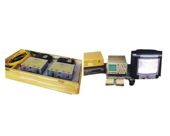
Code:EET2686
Optical Video Link Trainer provides study of Transmission and Reception of Video Signal via optical fiber. It consists of transmitter unit, Receiver unit, SC-SC path cord and other accessories to conduct experiments. VCD player, Colour Television, Function Generator & CRO are needed additionally. Transmitter module has video input optical output and test points. Receiver module has optical input, video output and test points. It can also be used to demonstrate optical video link using function Generator and CRO
Features
- Self Contained ready to use Video link.
- Applicable for Industrial Video link.
- Test Point provided on Transmitter and Receiver
Technical Specifications
- LASER Modulation at 1550nm.
Modulation Input
- 1 Video Signal
- 2 Function Generator Signal
Accessories Included:
- 1. Adaptor 12 DC 2Nos.
- 2. SC-SC Patch cord 1No.
- 3. Video Cables (Single) 2Nos.
- 4. BNC -2mm Cables 2Nos.
Experiments that can be performed:
- To compare video input signal and video output signal via optical video link
- To observe LASER modulator input signal and optical detector output signal
- To observe triangular, square, sine etc. Signal transmission via optical video link
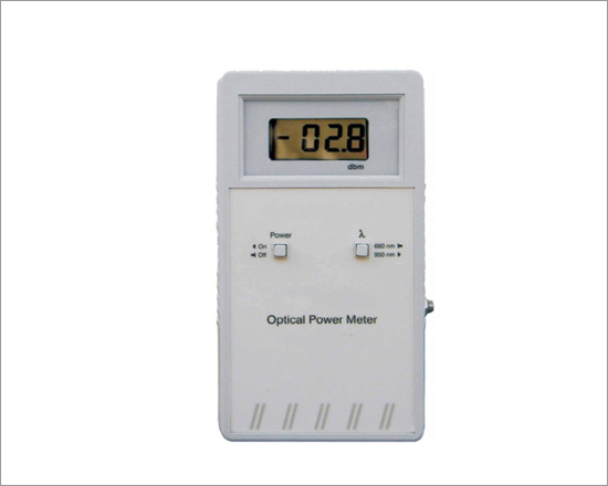
Optical Power Meter
Code:EET2691
Optical Power Meter is Hand Held Power Meter which provides performance, durability and stability formeasurement of optical power. Switches are provided for meter 'On/Off' and wavelength selection .The readings indicated on themeter are directly calibrated in dBm. The standard 9V battery is easily replaceable from the separated battery component on the backside of the meter
Features
- Input : 180 V Fixed DC
- Detector : Silicon detector
- Range : 0 dBm to -60 dBm
- Display : 12 mm LCD
- Wavelength : 660 & 950 nm*
- Connector : SMA
- Accuracy : 0.5 dBm
- Power : 9 V Battery
- Size (mm.) : W 100 × D 45 × H 175
- Learning material : Theory, procedure, reference results