Antenna,Satellite,GPS,Radar,RF


Educational Equipments Manufacturer, Exporters & Suppliers - School Educational Equipments Manufacturers & Exporters of Educational Equipments for Lab. Science Lab Products, Teaching Aids, Classroom Instruments, Educational Laboratory

Antenna Trainer with 11 Antennas

Code:EET0001

The desktop Antenna Training System Order Code-10008 has been specially designed for engineering colleges and training centers. It is very useful for introducing practical verification of antenna operation to the students. The work book provides theoretical concepts and detail procedure of experiments with each type of antenna.

The training system includes set of modular mechanical elements forming various antennas, a transmitter unit and a detector unit. All the accessories are packed in a convenient carrying case.

The Antenna Training System also comes with Motorised Antenna Unit (Model Order Code-10010) to automate the recording of the radiation pattern of the antennas. The Motorised Antenna Unit consists of a Microcontroller based system for Capturing, Displaying and Printing of Antenna radiation pattern. The system capture signal at an interval of 1° rotation using stepper motor and radiation pattern is displayed on PC . The Windows based Software is supplied in CD Rom. The PC Communication is via RS232 port. It used with Order Code-10010.

Technical Specifications
  • Waveforms : Sine
  • RF Generator : 750 MHz approximately (output adjustable)
  • Tone Generator : 1 KHz approximately (output adjustable)
  • Directional Coupler : Forward & Reverse (selectable)
  • Matching Stub : Slider type
  • Antenna Rotation : 0-360 deg. Resolution 1 deg.
  • Receiving Antenna : Folded dipole with reflector
  • Detector Display : Level adjustable meter
  • Interconnections : 2 mm Banana sockets
  • Power Supply : 230 V, ±10% 50/60 Hz
  • Power Consumption : 3 VA approximately
  • Operating Conditions : 0-400 C, 80% RH
  • Weight : 3 Kg approximately
  • Dimensions (mm) : W 385 x D 75 x H 285

Scope of Learning
  • Polar plots & polarization
  • Wave modulation & demodulation
  • Antenna gain, Antenna beam width study
  • Element current, Front-back ratio study
  • Antenna matching
  • Antenna radiation with distance

Features
  • Self Contained Simple and Student Friendly platform
  • Hands on set-up for measuring and plotting radiation Patterns of 20 different Antennas
  • On board RF & Tone Generators
  • Antenna Matching Stub
  • Characteristics and SWR Measurement
  • Transmitting and Receiving levels observed On Built- in Meters
  • Functional Block indicated On- board Mimics
  • Fully Documented Operating Manual and Polar Charts
  • "Antenna kit" for fabricating Special Antenna
  • Compact Design
  • Lightweight
  • 2 Year Warranty

List of Accessories (10 Antenna)
  • Antennas : 11 nos.
    - Simple Dipole l/2 : 1 no. - Yagi-UDA Folded Dipole (3E) : 1 no.
    - Yagi-UDA Folded Dipole (5E) : 1 no.
    - Yagi-UDA Simple Dipole (5E) : 1 no.
    - Yagi-UDA Simple Dipole (7E) : 1 no.
    - Hertz Antenna : 1 no.
    - Loop Antenna : 1 no.
    - Log Periodic Antenna : 1 no.
    - l/2 Phase Array : 1 no.
    - Detector Antenna : 1 no.
    - Helix Antenna : 1 no.
  • Current Probe : 1 no.
  • Transmitting Mast : 1 no.
  • RF Detector : 1 no.
  • Receiving Mast : 1 no.
  • Accessories Kit :
    - BNC - Tee : 1 no.
    - BNC - BNC Adapter (M) : 1 no.
    - BNC - BNC Adapter (F) : 1 no.
    - BNC (M) - BNC (F)
    - Adapter (L-type) : 1 no
    - BNC - BNC Cable 25" : 2 nos.
    - BNC - BNC Cable 18" : 1 no.
  • Polar Graphs (dBmA : 25 nos.
  • Polar Graphs
    - (for normalised reading) : 25 nos.
  • Antenna Fabrication Kit
    - Two PCB's : 1 no.
    - 14 SWG wire roll 20"
  • Mains Cord : 1 no.
  • +7.5 - 9V DC Adaptor(500mA) : 1 no.

Antenna Trainer with 22 Antennas

Code:EET0006

The desktop Antenna Training System Order Code- 10009 has been specially designed for engineering colleges and training centers. It is very useful for introducing practical verification of antenna operation to the students. The work book provides theoretical concepts and detail procedure of experiments with each type of antenna.

The training system includes set of modular mechanical elements forming various antennas, a transmitter unit and a detector unit. All the accessories are packed in a convenient carrying case.

The Antenna Training System also comes with Motorised Antenna Unit (Model Order Code-10010) to automate the recording of the radiation pattern of the antennas. The Motorised Antenna Unit consists of a Microcontroller based system for Capturing, Displaying and Printing of Antenna radiation pattern. The system capture signal at an interval of 1° rotation using stepper motor and radiation pattern is displayed on PC . The Windows based Software is supplied in CD Rom. The PC Communication is via RS232 port. It used with Order Code-10010.

Scope of Learning

  • Polar plots & polarization
  • Wave modulation & demodulation
  • Antenna gain, Antenna beam width study
  • Element current, Front-back ratio study
  • Antenna matching
  • Antenna radiation with distance

Features:

  • Self Contained Simple and Student Friendly platform
  • Hands on set-up for measuring and plotting radiation Patterns of
  • 20 different Antennas
  • On board RF & Tone Generators
  • Antenna Matching Stub
  • Characteristics and SWR Measurement
  • Transmitting and Receiving levels observed On Built- in Meters
  • Functional Block indicated On- board Mimics
  • Fully Documented Operating Manual and Polar Charts
  • "Antenna kit" for fabricating Special Antenna
  • Compact Design]Lightweight
  • 2 Year Warranty

Technical Specifications

  • Waveforms : Sine
  • RF Generator : 750 MHz approximately (output adjustable)
  • Tone Generator : 1 KHz approximately (output adjustable)
  • Directional Coupler : Forward & Reverse (selectable)
  • Matching Stub : Slider type
  • Antenna Rotation : 0-360 deg. Resolution 1 deg.
  • Receiving Antenna : Folded dipole with reflector
  • Detector Display : Level adjustable meter
  • Interconnections : 2 mm Banana sockets
  • Power Supply : 230 V, ±10% 50/60 Hz
  • Power Consumption : 3 VA approximately
  • Operating Conditions : 0-400 C, 80% RH
  • Weight : 3 Kg approximately
  • Dimensions (mm) : W 385 x D 75 x H 285

List of Accessories (10 Antenna)

  • Antennas : 11 nos.
    - Simple Dipole l/2 : 1 no.
    - Yagi-UDA Folded Dipole (3E) : 1 no.
    - Yagi-UDA Folded Dipole (5E) : 1 no.
    - Yagi-UDA Simple Dipole (5E) : 1 no.
    - Yagi-UDA Simple Dipole (7E) : 1 no.
    - Hertz Antenna : 1 no.
    - Loop Antenna : 1 no.
    - Log Periodic Antenna : 1 no.
    - l/2 Phase Array : 1 no.
    - Detector Antenna : 1 no.
    - Helix Antenna : 1 no.
  • Current Probe : 1 no.
  • Transmitting Mast : 1 no.
  • RF Detector : 1 no.
  • Receiving Mast : 1 no.
  • Accessories Kit :
    - BNC - Tee : 1 no.
    - BNC - BNC Adapter (M) : 1 no.
    - BNC - BNC Adapter (F) : 1 no.
    - BNC (M) - BNC (F)
    - Adapter (L-type) : 1 no
    - BNC - BNC Cable 25" : 2 nos.
    - BNC - BNC Cable 18" : 1 no.
  • Polar Graphs (dBmA : 25 nos.
  • Polar Graphs
    - (for normalised reading) : 25 nos.
  • IX. Antenna Fabrication Kit
    - Two PCB's : 1 no.
    - 14 SWG wire roll 20"
  • X. Mains Cord : 1 no.
  • XI. +7.5 - 9V DC Adaptor(500mA) : 1 no.
  • XII VIP Suitcase :1 no.
  • XIII. Rods for Ground Plane Antenna
    - 6.9cm : 1 no.
    - 8.5cm : 1 no.
    - 20.5cm : 1 no.

Motorised Antenna Trainer with Plotting Software and 22 Antennas

Code:EET0011

Technical Specifications

  • RF Input : From Order Code - 10008
  • Detector : Active with 5 pin DIN Connector
  • Antenna Rotation : 360° (Resolution 1.8°)
  • Power Supply : 230V ± 10%, 50/60 Hz
  • Power Consumption : 2 VA (approximately)
  • Dimensions (mm) : W 285 × D 390 × H 88
  • Weight : 3 Kg (approximately)
  • Accessories : Mains Cord, 5 Pin DIN cable,
  • Patch Cords, BNC-BNC Cable, RS232 Cable,
  • Radiation Pattern Plotting Software

Scope of Learning

  • Polar plots & polarization
  • Wave modulation & demodulation
  • Antenna gain, Antenna beam width study
  • Element current, Front-back ratio study
  • Antenna matching
  • Antenna radiation with distance

Features

  • Microconroller Based High Precision DC Stepper Motor
  • Automatic Zero Point setting
  • 4Built-in DC Power Supply
  • Instant Plotting of radiation Pattern
  • Resolution 1.80
  • RS232 data link to PC
  • Software running under Windows 98/ XP/ Window 7
  • 2 Year Warranty

List of Accessories (10 Antenna)

  • Antennas : 11 nos.
    - Simple Dipole l/2 : 1 no.
    - Yagi-UDA Folded Dipole (3E) : 1 no.
    - Yagi-UDA Folded Dipole (5E) : 1 no.
    - Yagi-UDA Simple Dipole (5E) : 1 no.
    - Yagi-UDA Simple Dipole (7E) : 1 no.
    - Hertz Antenna : 1 no.
    - Loop Antenna : 1 no.
    - Log Periodic Antenna : 1 no.
    - l/2 Phase Array : 1 no.
    - Detector Antenna : 1 no.
    - Helix Antenna : 1 no.
  • Current Probe : 1 no.
  • Transmitting Mast : 1 no.
  • RF Detector : 1 no.
  • Receiving Mast : 1 no.
  • Accessories Kit :
    - BNC - Tee : 1 no.
    - BNC - BNC Adapter (M) : 1 no.
    - BNC - BNC Adapter (F) : 1 no.
    - BNC (M) - BNC (F)
    -- Adapter (L-type) : 1 no
    - BNC - BNC Cable 25" : 2 nos.
    - BNC - BNC Cable 18" : 1 no.
  • Polar Graphs (dBmA : 25 nos.
  • Polar Graphs
    - (for normalised reading) : 25 nos.
  • Antenna Fabrication Kit
    - Two PCB's : 1 no.
    - 14 SWG wire roll 20"
  • Mains Cord : 1 no.
  • +7.5 - 9V DC Adaptor(500mA) : 1 no.
  • VIP Suitcase : 1 no.
  • Rods for Ground Plane Antenna
    - 6.9cm : 1 no.
    - 8.5cm : 1 no.
    - 3.20.5cm : 1 no.

Advanced Antenna Trainer with variable Frequency (550 MHz - 850 MHz) and 11 Antennas

Code:EET0016

Antenna platform Order Code -10011 is a student friendly trainer kit for studying characteristics of different antennas. Order Code -10011 is designed so that students can take the readings and plot the polar plots themselves, thus understanding the subject thoroughly. They can even stop & repeat the readings in between if needed.

All the antennas are made by high conducting rods with chrome finish for long durability and mounted on the glass epoxy PCB for easy mounting and dismounting Areas of Experimentation and Study

  • Polar plot & Polarization of various antennas.
  • Wave modulation and Demodulation
  • Antenna Gain
  • Antenna Beam Width.
  • Element Current study.
  • Front Back Ratio study.
  • Antenna matching.
  • SWR measurement.
  • Antenna radiation with distance.
  • Antenna bandwidth measurement

Features:

  • Self contained, simple and student friendly trainer
  • Hands on set-up for measuring and plotting radiation patterns of different Antennas
  • Built in RF & Modulation generators
  • Built in frequency display
  • Antenna Matching Stub
  • Characteristics and SWR measurement
  • Transmitting and Receiving levels observed on meters
  • Built in DC power supply
  • Fully documented, Operating manual and polar charts (2 types) with each trainer
  • "Antenna kit" for fabricating special antenna
  • Compact design
  • Light weight
  • 2 Year Warranty

Scope of Learning

  • Study of Simple Dipole l/2 Antenna
  • Performing Polarisation Test and Modulation Test
  • Study of Reciprocity Theorem
  • Study of variations in the radiation strength at a given distance from the antenna
  • Antenna Current Sensor and SWR Measurement
  • Study of Rhombus Antenna, Ground Plane Antenna, Slot
  • Antenna, Helix Antenna and antenna bandwidth

Technical Specifications

  • RF generator : 550 to 850 MHz approximately(with level adjust)
  • Modulation Generator : 1 KHz approximately (300 mV)
  • Directional Coupler : Forward & Reverse (On board selectable)
  • Matching Stub : Slide Stub
  • Antenna Rotation : 0- 360 Degree, Resolution 1 Degree Transmitting & Receiver masts provided
  • Receiving antenna : Folded Dipole with reflector
  • Detector Display : Adjustable meter
  • Interconnections : BNC
  • Power Supply : 230 V ±10%, 50/60 Hz
  • Power Consumption : 3VA (approximately
  • Weight : 3 kgs. Approximately
  • Dimensions (MainUnit-mm) : W 285 × H 75 × D 385

List of Accessories (11 Antenna)

  • Antennas : 11 nos.
    - Simple Dipole l/2 : 1 no.
    - Yagi-UDA Folded Dipole (3E) : 1 no.
    - Yagi-UDA Folded Dipole (5E) : 1 no.
    - Yagi-UDA Simple Dipole (5E) : 1 no.
    - Yagi-UDA Simple Dipole (7E) : 1 no.
    - Hertz Antenna : 1 no.
    - Loop Antenna : 1 no.
    - Log Periodic Antenna : 1 no.
    - l/2 Phase Array : 1 no.
    - Detector Antenna : 1 no.
    - Helix Antenna : 1 no.
  • Current Probe : 1 no.
  • Transmitting Mast : 1 no.
  • RF Detector : 1 no.
  • Receiving Mast : 1 no.
  • Accessories Kit :
    - BNC - Tee : 1 no.
    - BNC - BNC Adapter (M) : 1 no.
    - BNC - BNC Adapter (F) : 1 no.
    - BNC (M) - BNC (F)
    -- Adapter (L-type) : 1 no
    - BNC - BNC Cable 25" : 2 nos.
    - BNC - BNC Cable 18" : 1 no.
  • Polar Graphs (dBmA : 25 nos.
  • Polar Graphs
    - (for normalised reading) : 25 nos.
  • Antenna Fabrication Kit
    - Two PCB's : 1 no.
    - 14 SWG wire roll 20"
  • Mains Cord : 1 no.
  • +7.5 - 9V DC Adaptor(500mA) : 1 no.

Advanced Antenna Trainer with variable frequency (550 MHz - 850 MHz) and 22 Antennas

Code:EET0021

Antenna platform is a student friendly trainer kit for studying characteristics of different antennas. is designed so that students can take the readings and plot the polar plots themselves, thus understanding the subject thoroughly. They can even stop & repeat the readings in between if needed.

All the antennas are made by high conducting rods with chrome finish for long durability and mounted on the glass epoxy PCB for easy mounting and dismounting Areas of Experimentation and Study

  • Polar plot & Polarization of various antennas.
  • Wave modulation and Demodulation
  • Antenna Gain
  • Antenna Beam Width.
  • Element Current study.
  • Front Back Ratio study.
  • Antenna matching.
  • SWR measurement.
  • Antenna radiation with distance.
  • Antenna bandwidth measurement

Features

  • Self contained, simple and student friendly trainer
  • Hands on set-up for measuring and plotting radiation patterns of different Antennas
  • Built in RF & Modulation generators
  • Built in frequency display
  • Antenna Matching Stub
  • Characteristics and SWR measurement
  • Transmitting and Receiving levels observed on meters
  • Built in DC power supply
  • Fully documented, Operating manual and polar charts (2 types) with each trainer
  • "Antenna kit" for fabricating special antenna
  • Compact design
  • Light weight
  • 2 Year Warranty

Scope of Learning

  • Study of Simple Dipole l/2 Antenna
  • Performing Polarisation Test and Modulation Test
  • Study of Reciprocity Theorem
  • Study of variations in the radiation strength at a given distance from the antenna
  • Antenna Current Sensor and SWR Measurement
  • Study of Rhombus Antenna, Ground Plane Antenna, Slot
  • Antenna, Helix Antenna and antenna bandwidth

Technical Specifications

  • RF generator : 550 to 850 MHz approximately(with level adjust)
  • Modulation Generator : 1 KHz approximately (300 mV)
  • Directional Coupler : Forward & Reverse (On board selectable)
  • Matching Stub : Slide Stub
  • Antenna Rotation : 0- 360 Degree, Resolution 1 Degree Transmitting & Receiver masts provided
  • Receiving antenna : Folded Dipole with reflector
  • Detector Display : Adjustable meter
  • Interconnections : BNC
  • Power Supply : 230 V ±10%, 50/60 Hz
  • Power Consumption : 3VA (approximately
  • Weight : 3 kgs. Approximately
  • Dimensions (MainUnit-mm) : W 285 × H 75 × D 385

List of Accessories (10 Antenna)

  • Antennas : 11 nos.
    - Simple Dipole l/2 : 1 no.
    - Yagi-UDA Folded Dipole (3E) : 1 no.
    - Yagi-UDA Folded Dipole (5E) : 1 no.
    - Yagi-UDA Simple Dipole (5E) : 1 no.
    - Yagi-UDA Simple Dipole (7E) : 1 no.
    - Hertz Antenna : 1 no.
    - Loop Antenna : 1 no.
    - Log Periodic Antenna : 1 no.
    - l/2 Phase Array : 1 no.
    - Detector Antenna : 1 no.
    - Helix Antenna : 1 no.
  • Current Probe : 1 no.
  • Transmitting Mast : 1 no.
  • RF Detector : 1 no.
  • Receiving Mast : 1 no.
  • Accessories Kit :
    - BNC - Tee : 1 no.
    - BNC - BNC Adapter (M) : 1 no.
    - BNC - BNC Adapter (F) : 1 no.
    - BNC (M) - BNC (F)
    -- Adapter (L-type) : 1 no
    - BNC - BNC Cable 25" : 2 nos.
    - BNC - BNC Cable 18" : 1 no.
  • Polar Graphs (dBmA : 25 nos.
  • Polar Graphs
    - (for normalised reading) : 25 nos.
  • Antenna Fabrication Kit
    - Two PCB's : 1 no.
    - 14 SWG wire roll 20"
  • Mains Cord : 1 no.
  • +7.5 - 9V DC Adaptor(500mA) : 1 no.
  • VIP Suitcase : 1 no.
  • Rods for Ground Plane Antenna
    - 6.9cm : 1 no.
    - 8.5cm : 1 no.
    - 20.5cm : 1 no.

10 Antennas with Manual Rotation

Code:EET0026

Antenna Training System's have been designed to provide useful tools for hands on experimentation and teaching of various commonly used antennas in microwave band in the laboratory for students of all levels. Newly developed Antenna Training System's have been incorporated with a high end frequency operational range of 3GHz to 4GHz.

It can be used in stand-alone mode as well as be interfaced with a computer via USB interface. In this Receiving Antenna can be rotated from 0 to 360 Degrees and accordingly Receiving Antennas Signal strength can be monitored. The system consists of a set of tripod for mounting the transmitting and receiving antenna. There are 4 models with various options suited for all teaching methodology and curriculum.

Experiments:

  • Variation of field strength with distance
  • Plot radiation pattern of omni directional antenna
  • Plot radiation pattern of directional antenna
  • Polarization of vertical and horizontal antenna
  • Study resonant and non resonant antenna and estimate VSWR and impedance
  • Demonstrate reciprocity theorem of antennas
  • Study current distribution along the element of antenna
  • Study different antennas polar plots, radiation patterns, gain, beam width, front back ratio
  • Comparison of different antennas

Network Analyser : Transmitter & Receiver & Stepper Controller:

  • Frequency ---- 3000MHz - 4000MHz PLLsynthesized ---- Yes
  • Step Size ---- 0.1, 0.2, 0.5, 1, 20, 500 Mhz ---- Yes
  • Accuracy ---- 0.01% ---- Yes
  • Display ---- 16X2 Backlit LCD ---- Yes
  • Functions ---- Menu, Enter, Escape, Up & Down ---- Yes
  • Memory Location ---- 1000 individual frequencies and level can be stored/recalled ---- Yes
  • Output Impedance 50 Ohms ---- Yes
  • RF Level ---- 0 dBm Typical ---- Yes
  • Measurement ---- RF level in dBm with 0.1dB resolution ---- Yes
  • Dynamic Range ---- 60 dB Log ---- Yes
  • Auto Mode ---- Data logging for antenna gain & polar/cartesian plot ---- Yes
  • USB interface ---- Easy connectivity to PC using polar pattern plotting software ---- Yes
  • Power Supply ---- 230V @ 50 Hz ---- Yes
  • Rotation ---- 0-360 Degrees with 1 Deg resolution ---- No
  • Angular Steps ---- 1, 5, 10, 45 degrees ---- No
  • Functions ---- Menu, Enter, Escape, Up & Down ---- No
  • Memory ---- 1000 memories for storing angular positions for quick recall ---- No
  • Auto mode ---- Automatic Rotation with Interface to Receiver ---- No
  • Mode ---- Clockwise/Anti Clockwise Rotation, Fast /Slow Speed ---- No

Shipping List : Antennas & Other Accessories:

  • Microstrip Dipole L/2 ---- Yes
  • Microstrip Folded Dipole ---- Yes
  • Microstrip Yagi Uda (3E) ---- Yes
  • Microstrip Endfire Array L/2 ---- Yes
  • Microstrip Broadside Array L/2 ---- Yes
  • Monopole (Ground Plane) ---- Yes
  • Helix RHCP ---- Yes
  • Helix LHCP ---- Yes
  • Microstrip Inset fed Patch ---- Yes
  • Microstrip Transformer fed patch ---- Yes
  • Microstrip Square Loop ---- Yes
  • Microstrip Log Periodic ---- No
  • Microstrip Slot ---- No
  • Microstrip Series patch ---- No
  • Microstrip Dual patch array ---- No
  • Microstrip Circular patch ---- No
  • Microstrip Patch LHCP ---- No
  • Microstrip Patch RHCP ---- No
  • Microstrip Spiral ---- No
  • Microstrip Bow Tie Dipole ---- No
  • Microstrip Bow Tie CPW ---- No
  • Feed Horn ---- No
    -- Transmitter Tripod ---- Yes
    -- USB Connecting Lead ---- Yes
    -- Experimental Manual ---- Yes
    -- Voltage Probe ---- Yes
    -- Directional Coupler SMA(M)-SMA(M) ---- Yes
    -- Antenna Plotting Software CD ---- Yes

10 Antennas With Stepper Motor Automatic Rotation For Receiving Antenna

Code:EET0031

Antenna Training System's have been designed to provide useful tools for hands on experimentation and teaching of various commonly used antennas in microwave band in the laboratory for students of all levels. Newly developed Antenna Training System's have been incorporated with a high end frequency operational range of 3GHz to 4GHz.

It can be used in stand-alone mode as well as be interfaced with a computer via USB interface. In this Receiving Antenna can be rotated from 0 to 360 Degrees and accordingly Receiving Antennas Signal strength can be monitored. The system consists of a set of tripod for mounting the transmitting and receiving antenna. There are 4 models with various options suited for all teaching methodology and curriculum. Experiments:

  • Variation of field strength with distance
  • Plot radiation pattern of omni directional antenna
  • Plot radiation pattern of directional antenna
  • Polarization of vertical and horizontal antenna
  • Study resonant and non resonant antenna and estimate VSWR and impedance
  • Demonstrate reciprocity theorem of antennas
  • Study current distribution along the element of antenna
  • Study different antennas polar plots, radiation patterns, gain, beam width, front back ratio
  • Comparison of different antennas

Network Analyser : Transmitter & Receiver & Stepper Controller:

  • Frequency ---- 3000MHz - 4000MHz PLLsynthesized ---- Yes
  • Step Size ---- 0.1, 0.2, 0.5, 1, 20, 500 Mhz ---- Yes
  • Accuracy ---- 0.01% ---- Yes
  • Display ---- 16X2 Backlit LCD ---- Yes
  • Functions ---- Menu, Enter, Escape, Up & Down ---- Yes
  • Memory Location ---- 1000 individual frequencies and level can be stored/recalled ---- Yes
  • Output Impedance 50 Ohms ---- Yes
  • RF Level ---- 0 dBm Typical ---- Yes
  • Measurement ---- RF level in dBm with 0.1dB resolution ---- Yes
  • Dynamic Range ---- 60 dB Log ---- Yes
  • Auto Mode ---- Data logging for antenna gain & polar/cartesian plot ---- Yes
  • USB interface ---- Easy connectivity to PC using polar pattern plotting software ---- Yes
  • Power Supply ---- 230V @ 50 Hz ---- Yes
  • Rotation ---- 0-360 Degrees with 1 Deg resolution ---- Yes
  • Angular Steps ---- 1, 5, 10, 45 degrees ---- Yes
  • Functions ---- Menu, Enter, Escape, Up & Down ---- Yes
  • Memory ---- 1000 memories for storing angular positions for quick recall ---- Yes
  • Auto mode ---- Automatic Rotation with Interface to Receiver ---- Yes
  • Mode ---- Clockwise/Anti Clockwise Rotation, Fast /Slow Speed ---- Yes

Shipping List : Antennas & Other Accessories:

  • Microstrip Dipole L/2 ---- Yes
  • Microstrip Folded Dipole ---- Yes
  • Microstrip Yagi Uda (3E) ---- Yes
  • Microstrip Endfire Array L/2 ---- Yes
  • Microstrip Broadside Array L/2 ---- Yes
  • Monopole (Ground Plane) ---- Yes
  • Helix RHCP ---- Yes
  • Helix LHCP ---- Yes
  • Microstrip Inset fed Patch ---- Yes
  • Microstrip Transformer fed patch ---- Yes
  • Microstrip Square Loop ---- Yes
  • Microstrip Log Periodic ---- Yes
  • Microstrip Slot ---- Yes
  • Microstrip Series patch ---- Yes
  • Microstrip Dual patch array ---- Yes
  • Microstrip Circular patch ---- Yes
  • Microstrip Patch LHCP ---- Yes
  • Microstrip Patch RHCP ---- Yes
  • Microstrip Spiral ---- Yes
  • Microstrip Bow Tie Dipole ---- Yes
  • Microstrip Bow Tie CPW ---- Yes
  • Feed Horn ---- No
    -- Transmitter Tripod ---- Yes
    -- USB Connecting Lead ---- Yes
    -- Experimental Manual ---- Yes
    -- Voltage Probe ---- Yes
    -- Directional Coupler SMA(M)-SMA(M) ---- Yes
    -- Antenna Plotting Software CD ---- Yes

Antennas with Manual Rotation

Code:EET0036

Antenna Training System's have been designed to provide useful tools for hands on experimentation and teaching of various commonly used antennas in microwave band in the laboratory for students of all levels. Newly developed Antenna Training System's have been incorporated with a high end frequency operational range of 3GHz to 4GHz.

It can be used in stand-alone mode as well as be interfaced with a computer via USB interface. In this Receiving Antenna can be rotated from 0 to 360 Degrees and accordingly Receiving Antennas Signal strength can be monitored. The system consists of a set of tripod for mounting the transmitting and receiving antenna. There are 4 models with various options suited for all teaching methodology and curriculum. Experiments:

  • Variation of field strength with distance
  • Plot radiation pattern of omni directional antenna
  • Plot radiation pattern of directional antenna
  • Polarization of vertical and horizontal antenna
  • Study resonant and non resonant antenna and estimate VSWR and impedance
  • Demonstrate reciprocity theorem of antennas
  • Study current distribution along the element of antenna
  • Study different antennas polar plots, radiation patterns, gain, beam width, front back ratio
  • Comparison of different antennas

Network Analyser : Transmitter & Receiver & Stepper Controller:

  • Frequency ---- 3000MHz - 4000MHz PLLsynthesized ---- Yes
  • Step Size ---- 0.1, 0.2, 0.5, 1, 20, 500 Mhz ---- Yes
  • Accuracy ---- 0.01% ---- Yes
  • Display ---- 16X2 Backlit LCD ---- Yes
  • Functions ---- Menu, Enter, Escape, Up & Down ---- Yes
  • Memory Location ---- 1000 individual frequencies and level can be stored/recalled ---- Yes
  • Output Impedance 50 Ohms ---- Yes
  • RF Level ---- 0 dBm Typical ---- Yes
  • Measurement ---- RF level in dBm with 0.1dB resolution ---- Yes
  • Dynamic Range ---- 60 dB Log ---- Yes
  • Auto Mode ---- Data logging for antenna gain & polar/cartesian plot ---- Yes
  • USB interface ---- Easy connectivity to PC using polar pattern plotting software ---- Yes
  • Power Supply ---- 230V @ 50 Hz ---- Yes
  • Rotation ---- 0-360 Degrees with 1 Deg resolution ---- No
  • Angular Steps ---- 1, 5, 10, 45 degrees ---- No
  • Functions ---- Menu, Enter, Escape, Up & Down ---- No
  • Memory ---- 1000 memories for storing angular positions for quick recall ---- No
  • Auto mode ---- Automatic Rotation with Interface to Receiver ---- No
  • Mode ---- Clockwise/Anti Clockwise Rotation, Fast /Slow Speed ---- No

Shipping List : Antennas & Other Accessories:

  • Microstrip Dipole L/2 ---- Yes
  • Microstrip Folded Dipole ---- Yes
  • Microstrip Yagi Uda (3E) ---- Yes
  • Microstrip Endfire Array L/2 ---- Yes
  • Microstrip Broadside Array L/2 ---- Yes
  • Monopole (Ground Plane) ---- Yes
  • Helix RHCP ---- Yes
  • Helix LHCP ---- Yes
  • Microstrip Inset fed Patch ---- Yes
  • Microstrip Transformer fed patch ---- Yes
  • Microstrip Square Loop ---- Yes
  • Microstrip Log Periodic ---- No
  • Microstrip Slot ---- No
  • Microstrip Series patch ---- No/li>
  • Microstrip Dual patch array ---- No
  • Microstrip Circular patch ---- No
  • Microstrip Patch LHCP ---- No
  • Microstrip Patch RHCP ---- No
  • Microstrip Spiral ---- No
  • Microstrip Bow Tie Dipole ---- No
  • Microstrip Bow Tie CPW ---- No
  • Feed Horn ---- No
    -- Transmitter Tripod ---- Yes
    -- USB Connecting Lead ---- Yes
    -- Experimental Manual ---- Yes
    -- Voltage Probe ---- Yes
    -- Directional Coupler SMA(M)-SMA(M) ---- Yes
    -- Antenna Plotting Software CD ---- Yes

22 Antennas With Stepper Motor Automatic Rotation For Receiving Antenna

Code:EET0041

Antenna Training System's have been designed to provide useful tools for hands on experimentation and teaching of various commonly used antennas in microwave band in the laboratory for students of all levels. Newly developed Antenna Training System's have been incorporated with a high end frequency operational range of 3GHz to 4GHz.

It can be used in stand-alone mode as well as be interfaced with a computer via USB interface. In this Receiving Antenna can be rotated from 0 to 360 Degrees and accordingly Receiving Antennas Signal strength can be monitored. The system consists of a set of tripod for mounting the transmitting and receiving antenna. There are 4 models with various options suited for all teaching methodology and curriculum.

Experiments:

  • Variation of field strength with distance
  • Plot radiation pattern of omni directional antenna
  • Plot radiation pattern of directional antenna
  • Polarization of vertical and horizontal antenna
  • Study resonant and non resonant antenna and estimate VSWR and impedance
  • Demonstrate reciprocity theorem of antennas
  • Study current distribution along the element of antenna
  • Study different antennas polar plots, radiation patterns, gain, beam width, front back ratio
  • Comparison of different antennas

Network Analyser : Transmitter & Receiver & Stepper Controller:

  • Frequency ---- 3000MHz - 4000MHz PLLsynthesized ---- Yes
  • Step Size ---- 0.1, 0.2, 0.5, 1, 20, 500 Mhz ---- Yes
  • Accuracy ---- 0.01% ---- Yes
  • Display ---- 16X2 Backlit LCD ---- Yes
  • Functions ---- Menu, Enter, Escape, Up & Down ---- Yes
  • Memory Location ---- 1000 individual frequencies and level can be stored/recalled ---- Yes
  • Output Impedance 50 Ohms ---- Yes
  • RF Level ---- 0 dBm Typical ---- Yes
  • Measurement ---- RF level in dBm with 0.1dB resolution ---- Yes
  • Dynamic Range ---- 60 dB Log ---- Yes
  • Auto Mode ---- Data logging for antenna gain & polar/cartesian plot ---- Yes
  • USB interface ---- Easy connectivity to PC using polar pattern plotting software ---- Yes
  • Power Supply ---- 230V @ 50 Hz ---- Yes
  • Rotation ---- 0-360 Degrees with 1 Deg resolution ---- Yes
  • Angular Steps ---- 1, 5, 10, 45 degrees ---- Yes
  • Functions ---- Menu, Enter, Escape, Up & Down ---- Yes
  • Memory ---- 1000 memories for storing angular positions for quick recall ---- Yes
  • Auto mode ---- Automatic Rotation with Interface to Receiver ---- Yes
  • Mode ---- Clockwise/Anti Clockwise Rotation, Fast /Slow Speed ---- Yes

Shipping List : Antennas & Other Accessories:

  • Microstrip Dipole L/2 ---- Yes
  • Microstrip Folded Dipole ---- Yes
  • Microstrip Yagi Uda (3E) ---- Yes
  • Microstrip Endfire Array L/2 ---- Yes
  • Microstrip Broadside Array L/2 ---- Yes
  • Monopole (Ground Plane) ---- Yes
  • Helix RHCP ---- Yes
  • Helix LHCP ---- Yes
  • Microstrip Inset fed Patch ---- Yes
  • Microstrip Transformer fed patch ---- Yes
  • Microstrip Square Loop ---- Yes
  • Microstrip Log Periodic ---- Yes
  • Microstrip Slot ---- Yes
  • Microstrip Series patch ---- Yes/li>
  • Microstrip Dual patch array ---- Yes
  • Microstrip Circular patch ---- Yes
  • Microstrip Patch LHCP ---- Yes
  • Microstrip Patch RHCP ---- Yes
  • Microstrip Spiral ---- Yes
  • Microstrip Bow Tie Dipole ---- Yes
  • Microstrip Bow Tie CPW ---- Yes
  • Feed Horn ---- No
    -- Transmitter Tripod ---- Yes
    -- USB Connecting Lead ---- Yes
    -- Experimental Manual ---- Yes
    -- Voltage Probe ---- Yes
    -- Directional Coupler SMA(M)-SMA(M) ---- Yes
    -- Antenna Plotting Software CD ---- Yes

Satellite Communication Trainer

Code:EET0046

Satellite Communication platform provides an in-depth study of basic Satellite communication system. It consists of Uplink Transmitter, Satellite Link and Downlink Receiver, which can be conveniently placed in the laboratory. The Satellite can be placed at an elevated position if needed. The Satellite Transponder receives signal from Uplink Transmitter and retransmit at different frequencies to a Downlink Receiver. The Uplink and Downlink frequencies are selectable and can have variety of signals such as Video, Audio, Voice, Tone, Data and Telemetry (Temperature and Light intensity). The operating manual illustrates basic theory and glossary of Satellite Communication terms along with Experiments.

Features:

  • Transmitter with selectable frequency conversion
  • Simultaneous communication of three different signals
  • Communicate Audio, Video, Digital data, PC data, Tone,Voice, function generator waveforms etc.
  • 2414 - 2468MHz PLL microwave operation.
  • Communication of external broad band digital signal.
  • Choice of different transmitting and receiving frequencies.
  • Built-in Speaker and Microphone for Voice and Audio link.
  • Remote detection of Light intensity and environment temperature.
  • Detachable Dish Antenna at each station.
  • USB port for PC communication.
  • 2 Year Warranty.

Technical Specifications:
Uplink Transmitter

  • Transmitter with selectable frequency conversion
  • 2450-2468 MHz up-linking selectable frequencies
  • Wide band RF amplifier. No manual matching required.
  • 16 MHz Bandwidth
  • Frequency select switch and LED indication.
  • FM Modulation of Audio and Video.
  • Coverage area 35m Indoor and 100m outdoor
  • Transmit Audio, Video, Digital data, PC data, Tone, Voice, function generator waveforms etc.
  • Separate section for telemetry operation.

Inbuilt Tone Generator:

  • Frequency: 100Hz to 1 Khz.
  • Amplitude: 0V to 1Vpp.
  • Separate terminals provided for different inputs.
  • Power Supply: 230 VAC ±10 %, 50/60 Hz

Satellite Link:

  • Transponder with selectable Uplink and downlinks frequency conversion.
  • Light and Temperature sensors for telemetry operations.
  • Delay knob provided for simulated Transition delay experiment.
  • Optional Solar power supply for Transponder Unit.
  • Detachable Dish Antennas.
  • Power Supply: 230 VAC ±10 %, 50/60 Hz

Downlink Receiver:

  • Receiver with selectable frequency conversion.
  • Receives and demodulate three signals simultaneously.
  • Built in speaker for audio and video output.
  • Detachable Dish Antenna.
  • ower Supply: 230 VAC ±10 %, 50/60 Hz

Scope of Learning:

  • Transmitting & receiving three separate Signals (Audio, Video, and Tone/ Voice) simultaneously through satellite link and perform Link Fail Operations.
  • Transmitting & receiving Function Generator Waveforms through Satellite Link.
  • Transmitting and receiving PC data through satellite link.
  • Study the delay between Uplink transmitter and Downlink receiver during data transmission.
  • Send Tele-command and receive Temperature & intensity of light from satellite.
  • Calculate the carrier to noise ratio for a satellite link.
  • Calculate signal to noise ratio for a satellite link.

Included Accessories

  • Audio-Video Cable 2 Pin 2 nos.
  • Patch Cord 16"(4mm) 2 nos.
  • Microphone 1 no.
  • Dish Antenna 4 nos.
  • USB Cable 2 nos.
  • Pencil Cell (Microphone) 1 no.
  • Mains Cord 3 nos.
  • PC Software 1 no.

Radar Trainer

Code:EET0051

The Radar Trainer is a very useful and realistic classroom training equipment. provided with different types of accessories for experimentation and a Windows® based software for observation and calculation of different parameters. On-board Test points are provided which enable students to observe the signals on an Oscilloscope or a PC. The trainer is capable to measure the Speed of object, Frequency of vibrations and RPM of any fan. Students can also study the properties of different types of material like Metal, Acrylic, Teflon, Bakelite, etc.

Technical Specifications

  • Transmitter Frequency : 10 GHz
  • Output Power : 10 mW (approximate)
  • Operating Voltage : 8.6 V
  • Antenna : Horn
  • Antenna Gain : 16dB
  • Sensitivity : -50 to -70dBm
  • IF Output : Audio range
  • Power Supply : 230 V±10%, 50 Hz
  • Alarm : Onboard

About Software

  • Oscilloscope : Real time/Storage mode with FFT analysis
  • Display : Voltage : Vpp
  • Speed : Km/hr, Miles/hr, m/s, rpm
  • Frequency: Hz & kHz
  • Time domain window : Display the Doppler Frequency in Time domain
  • Frequency domain window : Display the Doppler Frequency in Frequency domain
  • Control Panel window :
  • User interface for :
  • Measurement of Doppler
  • Frequency, Amplitude
  • Measurement of Velocity, RPM

Features :

  • Complete hardware and software setup to demonstrate Radar concepts
  • Signals study on Software / Oscilloscope with the help of test points given on trainer
  • Object counter provided on trainer
  • Real time fan RPM measurements and vibrations measurements with the help of tuning forks
  • Tripod stand provided for height and level matching
  • LED Indication for Doppler Echo Signal
  • On board alarm for detected signals

Utilities :

  • Start / Stop of Display
  • Setting of Time base and Amplitude range on display window
  • Printing of Doppler Frequency signal
  • Cursors for Time & Voltage measurements Save, Load

Scope of Learning

  • Study of the working of a Doppler Radar
  • Study of determine the Velocity of the object moving in the Radar range
  • Study of understand the principle of Doppler Radar of Time and Frequency measurement with the help of moving pendulum
  • Study of an Alarm System by using Radar
  • Study the Object Counting with the help of Radar
  • Study of the detection of vibration of different Tuning forks
  • Determine the rotation per minute (RPM) of a moving object (Fan)Study of the effect of different types of materials on Radar reception or detection

Included Accessories

  • Trainer Board -----------------------------------------1
  • Audio Cable for PC Line In input -----------------1
  • Din connector cable (5 Pin) ------------------------1
  • Mains Cord -------------------------------------------1
  • Tripod Stand -----------------------------------------1
  • Fan Stand ---------------------------------------------1
  • Fan -----------------------------------------------------1
  • Sliding Platform -------------------------------------1
  • Different objects -------------------------------------3
  • Horn Antenna ----------------------------------------1
  • Trans-receiver Unit ----------------------------------1
  • Software CD ------------------------------------------1
  • Pendulum --------------------------------------------1
  • Stand for moving the pendulum -------------------1
  • Tuning forks ------------------------------------------3
  • Operation manual ------------------------------------1

GPS Trainer

Code:EET0056

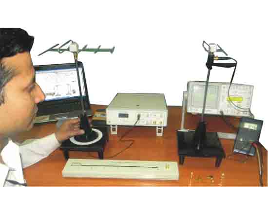
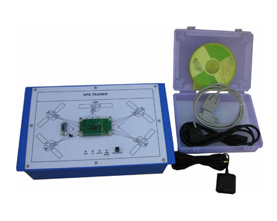
GPS Trainer Global Positioning System technology is rapidly changing how people find their way around the earth. Whether it is for fun, saving lives, getting there faster, or whatever uses you can dream up, GPS navigation is becoming more common everyday. GPS Trainer will provide a basic understanding of the GPS Fundamentals, Satellites & Design Aspects of GPS Receiver by actually connecting to the Satellite by GPS Antenna.

The Equipment is Useful for Students at B.Tech/B.S. & M.S level in engineering / technical institutes (EC & Telecom) Technical training centers in communication organizations, R&D personal and practicing engineering in research labs and industry.

Object
Experiments that can be performed

  • Understanding concept of GPS
  • Establishing Link between GPS Satellite & GPS Trainer
  • Measurement of Latitude & Longitude
  • To Study Effect of DOP
  • Study of HDOP & VDOP
  • Analysis of Elevation Azimuth SNR
  • Study of PRN code
  • Study of Common NMEA Sentence Protocol like, GPGGA, GPGLL, GPGSA, GPGSV, GPRMC, GPVTG
  • Study of other GPS NMEA Sentenses like, GPALM, GPGRS, GPGST, GPMSS, GPZDA
  • Study of useful Conversion formulas
  • Analysis of NMEA 0183 protocols
  • Study of UTC data and time

Specification & Features

  • Channel : 12
  • Frequency : L1 C/A
  • Position Accuracy : 25 meters CEP without SA
  • Velocity Accuracy : 0.1 meters/second, without SA Off
  • Time Accuracy : Synchronized to GPS time
  • Update rate : 1/sec. (1 PPS) signal
  • Receiver Sensitivity : -175 dBW
  • Input Voltage : +5VDC
  • Current (Avg.) Push Button for Reset : 180 mA
  • Serial Communication : 4800 Baud (default)
  • Protocol Messenger : NMEA0183V2.2,SIRF binary & RTCMSC -104V 2.0 type 1,2,9
  • Maximum Altitude : 18000 meters (60,000 Feet) max.
  • Maximum speed : 515 meters/sec. (1000 knots)max.
  • Acceleration : 4g. maximum
  • Jerk : 20 meters/sec-3 max.
  • Time to First Fix PC Interface - RS 232 Port: 45 / 38 / 8sec Cold/Warm/Hot Start
  • Operating Temperature : -40° C to +85° C
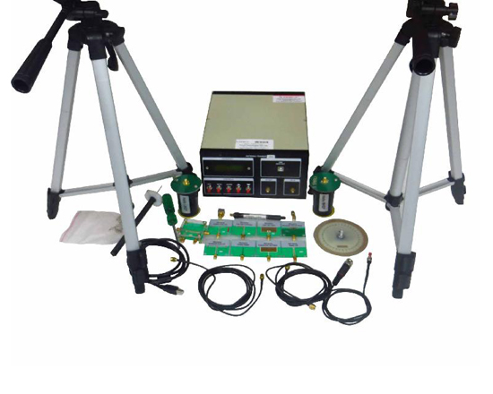
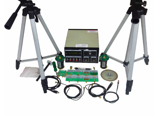
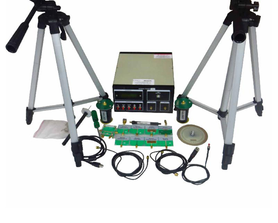
Gps Accessories

  • Serial Cable M/F
  • Mains lead
  • GPS Antenna
  • Software CD

Other Apparatus Required

  • PC with Window XP


Educational Equipments
Biology Lab Microscopes Physics Lab Chemistry Lab
Lab Glassware Chinaware & Porcelain ware Lab Platinum-ware Lab Plasticware Stands, Racks, Clamps Wooden Racks and Stands Electro-Chemistry Power Supplies Electrical Spares & Supplies Molecular Models Organic Chemistry Set Laboratory Balances
/ Lab Measuring Instruments
Measurement Aids Spatula Lab Rubber Tubing Chemistry Lab Consumables Lab Brushes Hand Tools and Others Gas Tap & Fittings Lab Testing Papers Chemistry Lab Models Chemistry Charts Lab Safety Supplies Thermometers Laboratory Chemicals
Lab Microscopes & Slides Laboratory Glassware Lab Plasticware Mathematics Lab School/College Science Kits Geography & Geology Teaching Equipments Educational Charts Whiteboard & Boards
Lab Measuring Instruments Electronics Lab Engineering Lab Testing Lab (Engineering) Astronomy Lab Equipments Civil Engineering Equipments Civil Engineering Models Scientific Lab Instruments Blood Bank Equipments Educational Charts