Educational Equipments Manufacturer, Exporters & Suppliers - School Educational Equipments Manufacturers & Exporters of Educational Equipments for Lab. Science Lab Products, Teaching Aids, Classroom Instruments, Educational Laboratory
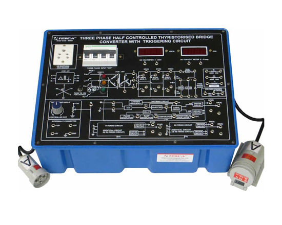
Three Phase Half Controlled Thyristorized Bridge ConverterWith Triggering Circuit
Code:EET3501
Power Electronic Training Board has been designed specifically for the study of Three Phase Half Controlled Thyristorized Bridge Converter with Triggering Circuit. Practical experience on this board carries great educative value for Science and Engineering Students.
Object
- To study the nature and generation of Control Signal for 3 phase Half wave Controlled Rectifier.
* To study the operation of a 3f Half Wave controlled bridge rectifier with R load.
* To study the operation of a 3f Half Wave controlled bridge rectifier with R-L load.
* To study the effect of free wheeling diode on the output waveform.
Features
The board consists of the following built-in parts:
- Three Phase line commuted fully-controlled thyristorized bridge converter.
- Three pole power contractor with AC coil complete with Push-to-ON switch.
- Four pole Miniature Circuit Breaker (MCB).
- Three separate idendical cards consisting of Zero Crossing Detector, Integrator, Comprator and Pulse Generator one for each phase, for controlling the triggering angles of the positive group of three thyristors.
- Firing angle control potentiometer.
- Three 415 : 6 VTransformers AC supply for Triggering.
- Three 415 : 50 V at 1 Amp Transformer for rectification
- ± 12V & +5V DC at 500mA, IC Regulator Power Supply for Triggering Circuits.
- Three nos. Driver Circuits with Pulse Transformers.
- High Frequency Gated Dual Gate Firing 3 nos.
- R and L load with Load voltage divider.
- Two 3½ digital panel meter (DPM) for measurement of voltage and current.
- One freewheel diode.
- Unearthed mains sockets for CRO.
- Adequate no. of other electronic components.
- The jewel light in Red, Blue & Yellow colour.
- The unit is operative on 3-f 415V at 50Hz A.C. Mains.
- Adequate no. of patch cords stackable from rear both ends 4mm spring loaded plug length 1/2 metre.
- Good Quality, reliable terminal/sockets are provided at appropriate places on panel for connections/observation of waveforms.
- Strongly supported by detailed Operating Instructions, giving details of Object Theory, Design procedures, Report Suggestions and Book References.
- Weight : 15Kg. (Approx.)
- Dimension : W 445 x H 260 x D 470
Other Apparatus Required:
- Dual Trace Cathode Ray Oscilloscope 20MHz (Unearthed)
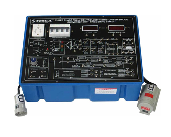
Three Phase Fully Controlled Thyristorized Bridge Converter With Triggering Circuit
Code:EET3506
Power Electronic Training Board has been designed specifically for the study of Three Phase Fully Controlled Thyristorized Bridge Converter with Triggering Circuit. Practical experience on this board carries great educative value for Science and Engineering Students.
Object
- To study the nature and generation of Control Signal for 3 phase Full-wave Controlled Rectifier.
- To study the operation of a 3 phase Full-wave Controlled Bridge Rectifier with R load.
- To study the operation of a 3 phase Full-wave Controlled Bridge Rectifier with R-L load.
- To study the effect of Free Wheeling Diode on the output waveform.
Features
The board consists of the following built-in parts:
- Three Phase line commuted fully-controlled thyristorized bridge converter.
- Three pole power contractor with AC coil complete with Push-to-ON switch.
- Four pole Miniature Circuit Breaker (MCB).
- Three separate idendical cards consisting of Zero Crossing Detector, Integrator, Comparator and Pulse Generator one for each phase, for controlling the triggering angles of the positive group of three thyristors. Another card in conjunction with above three cards for controlling the triggering angles of the negative group of three thyristors.
- Firing angle control potentiometer.
- Three 415 : 6 VTransformers AC supply for Triggering.
- Three 415 : 50 V at 1 Amp Transformer for rectification
- ± 12V at 500mA, IC Regulator Power Supply for Triggering Circuits.
- 5V at 500mA, IC Regulator Power Supply for Triggering Circuits.
- Six nos. Driver Circuits with Pulse Transformers.
- High Frequency Gated Dual Gate Firing 6 nos.
- R and L load with Load voltage divider.
- Two 3½ digital panel meter (DPM) for measurement of voltage and current.
- One freewheel diode.
- Unearthed mains sockets for CRO.
- Adequate no. of other electronic components.
- Three Jewel light in red, Yellow and Blue Colour
- The unit is operative on 3-f 415V at 50Hz A.C. Mains.
- Adequate no. of patch cords stackable from rear both ends 4mm spring loaded plug length 1/2 metre.
- Good Quality, reliable terminal/sockets are provided at appropriate places on panel for connections/observation of waveforms.
- Strongly supported by detailed Operating Instructions, giving details of Object Theory, Design procedures, Report Suggestions and Book References.
- Weight : 15Kg. (Approx.)
- Dimension : W 445 x H 260 x D 470
Other Apparatus Required:
- Dual Trace Cathode Ray Oscilloscope 20MHz (Unearthed)
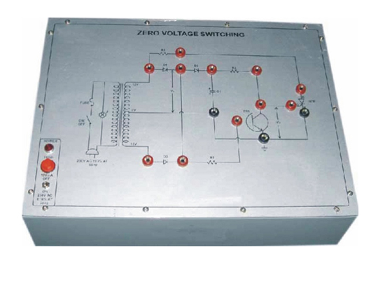
Zero Voltage Switching
Code:EET3511
Power Electronic Training Board has been designed specifically for the study of Zero voltage switching board.Practical experience on this board carries great educative value for Science and Engineering Students.
Object
- To study operation of zero voltage switching of thyristor.
Features
The board consists of the following built-in parts:
- A transformer to give low AC voltage to Thyristor and DC voltage to transistor.
- Two diode used as fullwave rectifier.
- One diode to avoid -ve voltage to collector of NPN transistor.
- A NPN transistor.
- AThyristor.
- Adequate no. of other electronic components.
- Mains ON/OFF switch, Fuse and Jewel light.
- The unit is operative on 230V ±10% at 50Hz A.C. Mains.
- Good Quality, reliable terminal/sockets are provided at appropriate places on panel for connections/observation of waveforms.
- Strongly supported by detailed Operating Instructions, giving details of Object Theory, Design procedures, Report Suggestions and Book References.
- Weight : 3Kg. (Approx.)
- Dimension : W 340 x H 110 x D 210
Other Apparatus Required:
- Digital Multimeter - Order Code 16901
- Dual Trace Cathode Ray Oscilloscope 20MHz (Unearthed/with isolation transformer for unearthing).
Power Transistor Characteristics

Code:EET3516
Power Electronic Training Board has been designed specifically to study Power Transistor input and output Characteristics in common Emitter Configuration and Switching Characteristics of NPN Transistor. The board is absolutely self contained. Practical experience on this board carries great educative value for Science and Engineering Students.
Object
- To study & plot the Input Characteristics of Power Transistor in Common Emitter Configuration.
- To study & plot the Output Characteristics of Power Transistor in Common Emitter Configuration.
- To study the Switching Characteristics of Power Transistor .
Features
The board consists of the following built-in parts:
- Regulated power supply 0-5V at 30mA with coarse and fine voltage variation.
- IC Regulated power supply, 0-30V at 100 mA .
- Digital DC voltmeter with selectable switch range 0 - 2/20V.
- Digital DC voltmeter ranges 0-200 V DC.
- Digital DC Ammeter with selectable switch range 0-2/20 mA.
- Digital DC Ammeter with selectable switch range 0-20/200 mA.
- Power Transistor
- Adequate no. of other electronic components.
- Mains ON/OFF switch, Fuse and Jewel light.
- The unit is operative on 230V ±10% at 50Hz A.C. Mains.
- Adequate no. of patch cords stackable from rear both ends 4mm spring loaded plug length 1/2 metre.
- Good Quality, reliable terminal/sockets are provided at appropriate places on panel for connections/observation of waveforms.
- Strongly supported by detailed Operating Instructions, giving details of Object Theory, Design procedures, Report Suggestions and Book References.
- Weight : 6Kg. (Approx.)
- Dimension : W 412 x H 150 x D 310
Other Apparatus Required:
- Dual Trace Cathode Ray Oscilloscope 20MHz.
- Function Generator
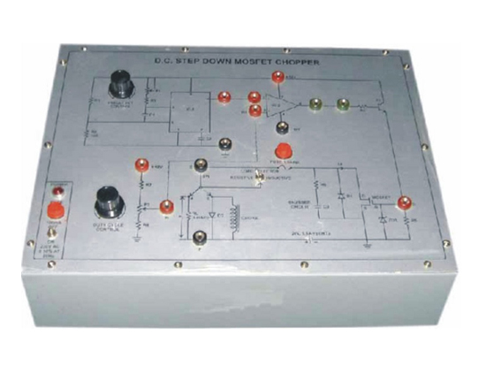
D.C. Step Down Mosfet Chopper
Code:EET3521
Looking to the recent requirement of educational institutions, we have developed Omega Tyep PET-446. D.C. Step down mosfet chopper.Practical experience on this board carries great educative value for Science and Engineering Students.
Object
- To study D.C. Step down Mosfet Chopper.
Features
The board consists of the following built-in parts:
- ± 12 Volt D.C. at 100mA, regulated Power Supply.
- 20 Volt DC at 1A, regulated Power Supply.
- IC for triangular pulse generation.
- IC to drive MOSFET.
- MOSFET.
- Two potentiometer for varying frequency and duty cycle.
- Adequate no. of other electronic components.
- Mains ON/OFF switch, Fuse and Jewel light.
- The unit is operative on 230V ±10% at 50Hz A.C. Mains.
- Adequate no. of patch cords stackable from rear both ends 4mm spring loaded plug length 1/2 metre.
- Good Quality, reliable terminal/sockets are provided at appropriate places on panel for connections/observation of waveforms.
- Strongly supported by detailed Operating Instructions, giving details of Object Theory, Design procedures, Report Suggestions and Book References.
- Weight : 5Kg. (Approx.)
- Dimension : W 300 x H 140 x D 200
Other Apparatus Required:
- Dual Trace Cathode Ray Oscilloscope 20MHz. (Unearthed).
D.C. To A.C. Inverter (Input 12V DC 80AH Output 230VAC, 40W)
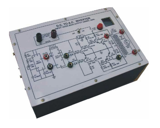
Code:EET3526
Power Electronic Training Board has been designed specifically for the study of working of inverter. A Battery 12V 80AH(Any car battery) is required to operate this apparatus. Different test points have been provided to check waveshape and amplitude of pulses how DC supply is changed to AC supply.Practical experience on this board carries great educative value for Science and Engineering Students.
Object
- To study the multivibrator circuit to convert DC to AC
Features
The board consists of the following built-in parts:
- IC-1 & IC-2 to generate AC signals to drive
- 12-0-12VAC at 4 Amp. Transformer.
- Four NPN low Power Transistors.
- Four NPN high Power Transsistors
- Red, Black and Green terminals for test points.
- Lamp holder and Lamp 40W, 230V.
- Unit is operative on 12 volt 80AH Battery (Any Car Battery).
- Sufficient quantity of patch cords.
- Good Quality, reliable terminal/sockets are provided at appropriate places on panel for connections/observation of waveforms.
- Strongly supported by detailed Operating Instructions, giving details of Object, Theory, Design procedures, Report Suggestions and Book References.
- Weight : 6Kg. (Approx.)
- Dimension : W 300 x H 140 x D 200
Other Apparatus Required:
- Battery 12V DC 80AH (Any Car Battery).
- Digital Multimeter - Order Code 16901
- Dual Trace Cathode Ray Oscilloscope 20MHz (Unearthed).
Step Up & Step Down Transistor Chopper
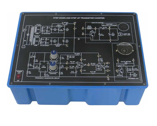
Code:EET3531
To study Step Up & Step Down Chopper. Practical experience on the board carries great educative value for Science and Engineering Students.
Object
- To study Step Up & Step Down Transistor Chopper.
Features
The board consists of the following built-in parts:
- +12V DC at 1.5 Amp, IC Regulated Power Supply internally connected.
- -12V DC at 200 mA, IC Regulated Power Supply internally connected.
- IC for Triangular wave pulse generation.
- OPamplifier.
- Choke 40mH.
- Lamp 230V 15watt.
- DC Motor 12 V.
- Adequate no. of other electronic components.
- Mains ON/OFF switch, Fuse and Jewel light.
- The unit is operative on 230V ±10% at 50Hz A.C. Mains.
- Adequate no. of patch cords stackable from rear both ends 4mm spring loaded plug length 1/2 metre.
- Good Quality, reliable terminal/sockets are provided at appropriate places on panel for connections/observation of waveforms.
- Weight : 5Kg. (Approx.)
- Dimension : W 412 x H 150 x D 310
Other Apparatus Required:
- Dual Channel Cathode Ray Oscilloscope 20MHz.
Study & Plot V/I Characteristic of Power IGBT
Code:EET3536
To study & Plost VI Characteristic of Power IGBT. The board is absolutely self contained.Practical experience on this board carries great educative value for Science and Engineering Students.
Object
- To study and Plot V/I Characteristic of a Power IGBT.
- Switching characteristic of a power IGBT
Features
The board consists of the following built-in parts:
- IC regulated power supply 0-10V DC at 30mA.
- IC regulated power supply 0-60V at 200mA.
- Digital DC voltmeter range 0-20V
- Digital DC voltmeter range 0-200V.
- Digital DC Ammeter with selectable switch range 0-20/200mA.
- One IGBT.
- Adequate no. of other electronic components.
- Mains ON/OFF switch, Fuse and Jewel light.
- The unit is operative on 230V ±10% at 50Hz A.C. Mains.
- Adequate no. of patch cords stackable from rear both ends 4mm spring loaded plug length 1/2 metre.
- Good Quality, reliable terminal/sockets are provided at appropriate places on panel for connections/observation of waveforms.
- Strongly supported by detailed Operating Instructions, giving details of Object Theory, Design procedures, Report Suggestions and Book References.
- Weight : 5Kg. (Approx.)
- Dimension : W 300 x H 140 x D 200
Other Apparatus Required:
- Dual Trace Cathode Ray Oscilloscope 20MHz.
- Function generator
Stepper Motor Control Using IC SAA-1027
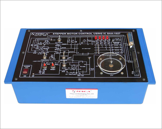
Code:EET3541
Stepper Motor Control trainer are based on IC SAA-1027 & designed to study the various functions of a stepper motor. It can be interfaced with microprocessor trainer and persnol computer. Practical experience on this board carries great educative value for Science and Engineering Students.
Object
- To study various functions of Stepper Motor
Features
The board consists of the following built-in parts:
- DC Stepper Motor 4 winding torque 1.0 Kg-cm, step angle 1.8°, power 12V 0.2 Amp/ phase
- Fast & slow selection switch
- Forward & reverse selection switch
- Free run & step selection switch
- Microprocessor/ PC and on board selector switch built in option for microprocessor interfacing/ personal computer
- IC regulated 12V DC at 500mA
- Timer IC LM 555
- Driver IC SAA-1027
- Adequate no. of other electronic components.
- Mains ON/OFF switch, Fuse and Jewel light.
- The unit is operative on 230V ±10% at 50Hz A.C. Mains.
- Good Quality, reliable terminal/sockets are provided at appropriate places on panel for connections/observation of waveforms.
- Strongly supported by detailed Operating Instructions, giving details of Object Theory, Design procedures, Report Suggestions and Book References.
- Weight : 3Kg. (Approx.)
- Dimension : W 340 x H 110 x D 210
Study of Buck Boost Principle
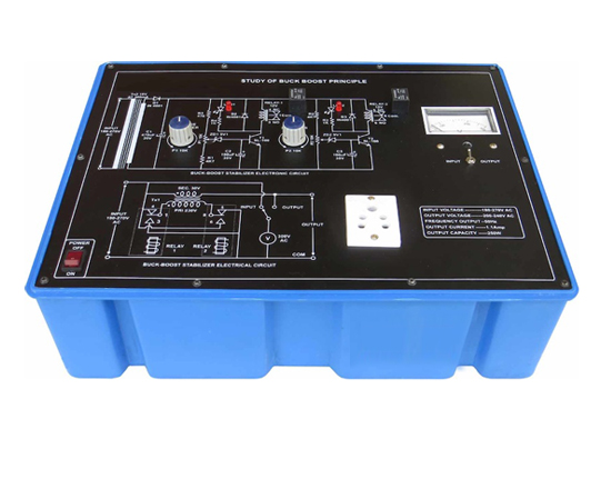
Code:EET3546
Study of buck boost principle has been designed with a view to provide practical/experimental knowledge of Automatic two step Buck Boost Principle with electronically controlled circuit. All the components and test points of the Principle are spread on the panel at appropriate places. A diagram is neatly drawn on the panel. Practical experience on this board carries great educative value for Science and Engineering Students.
Object
- To demonstrate the Buck Boost principle.
- To demonstrate the lower voltage setting.
- To demonstrate the upper voltage setting.
- To demonstrate automatic voltage stabilization of A.C. Voltage.
Features
- The unit consists of Automatic two step Buck-Boost Principle with electronically controlled circuit.
- Strongly supported by detailed Operating Instructions, giving details of Object, Theory, Design procedures, Report Suggestions and Book References.
- INPUT VOLTAGE : 180-270 Volt AC
- OUTPUT VOLTAGE : 200-240 Volt AC
- FREQUENCY : 50 Hz
- OUTPUT CURRENT : 1.1 Amp.
- CAPACITY : 250 Watt
- Weight : 5Kg. (Approx.)
- Dimension : W 412 x H 150 x D 310
Other Apparatus Required:
Study of Current Transformer (C.T.)
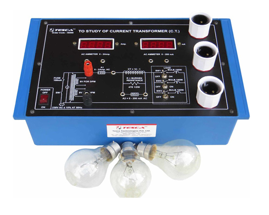
Code:EET3551
Power Electronic Training Board has been designed specifically to study Current Transformer ( C.T. ). Practical experience on this board carries great educative value for Science and Engineering Students.
Object
- To study Current Transformer.( C.T. )
Features
The board consists of the following built-in parts:
- Current Transformer INPUT current is 2 Amp & OUTPUT current 200 mA i.e. Ratio 10 : 1.
- Digital AC Ammeter 31/2 digits seven segment display having range 0-2A.
- Digital AC Ammeter 31/2 digits seven segment display having range 0-200mA.
- Three 100 W Bulbs have been provided for load. Controlled by three different switches.
- Adequate no. of other electronic components.
- Mains ON/OFF switch, Fuse and Jewel light.
- The unit is operative on 230V ±10% at 50Hz A.C. Mains.
- Adequate no. of patch cords stackable 4 mm spring loaded plug length ½ meter.
- Good Quality, reliable terminal/sockets are provided at appropriate places on panel for connections/observation of waveforms.
- Strongly supported by detailed Operating Instructions, giving details of Object Theory, Design procedures, Report Suggestions and Book References.
- Weight : 3Kg. (Approx.)
- Dimension : W 340 x H 110 x D 210
Other Apparatus Required:
- VARIAC INPUT 230 VAC OUTPUT 0-270 VA.C. at 2 Amps.
Study of Potential Transformer (P.T.)
Code:EET3556
Power Electronic Training Board has been designed specifically to study Potential Transformer (P.T.) Practical experience on this board carries great educative value for Science and Engineering Students.
Object
- To study Potential Transformer (P.T.)
Features
The board consists of the following built-in parts:
- Potential Transformer is designed for 300 VAC INPUT & OUTPUT 30 VAC i.e. ratio 10 : 1.
- Digital AC voltmeter 0-1000V.
- Digital AC voltmeter 0-200V.
- Mains ON/OFF switch, Fuse and Jewel light.
- The unit is operative on 230V ±10% at 50Hz A.C. Mains.
- Adequate no. of patch cords stackable 4 mm spring loaded plug length ½ meter.
- Good Quality, reliable terminal/sockets are provided at appropriate places on panel for connections/observation of waveforms.
- Strongly supported by detailed Operating Instructions, giving details of Object Theory, Design procedures, Report Suggestions and Book References.
- Weight : 3Kg. (Approx.)
- Dimension : W 340 x H 110 x D 210
Other Apparatus Required:
- Variac INPUT 230 V OUTPUT 0-270 Volt at 2 Amps.
Study of Instrument Transformers (C.T & P.T.)
Code:EET3561
Power Electronic Training Board has been designed specifically to study the working and application of instrument transformer. Measurement of power using Current and Potential Transformers. The setup consists of current Transformer, Potential Transformer, Ammeter, Voltmeter, Watt meter, Variac and Actual Load.Practical experience on this setup carries great educative value for Science and Engineering Students.
Object
- Current Transformer (C.T.)
- Potential Transformer (P.T.)
- To connect instrument transformers (C.T. & P.T.) in electrical circuits for measurement of current, voltage and power.
Features
The board consists of the following built-in parts:
- Current Transformer (CT) ratio 1 : 10.
- Potential Transformer (PT) ratio 10 : 1.
- Two digital AC voltmeter 3½ digit seven segment display. To read 1000V ac and 200V ac.
- Two digital AC ammeter 3½ digit seven segment display. To read amp. ac and 200mA ac.
- Digital low power factor watt meter single phase single eliment two wire normal input 230 V ( 0 - 120% ) of normal input current ( 0 - 0.5 Amp ) ( 0 - 125% )
- Actual load 300Watt (Three 100 Watt Bulbs and Three switches)
- The unit operate 230V ±10% at 50 Hz AC Mains
- Mains ON/OFF switch, Fuse and Jewel light.
- The unit is operative on 230V ±10% at 50Hz A.C. Mains.
- Adequate no. of patch cords stackable 4 mm spring loaded plug length ½ meter.
- Good Quality, reliable terminal/sockets are provided at appropriate places on panel for connections/observation of waveforms.
- Strongly supported by detailed Operating Instructions, giving details of Object Theory, Design procedures, Report Suggestions and Book References.
- Weight : 5Kg. (Approx.)
- Dimension : W 412 x H 150 x D 310
Other Apparatus Required:
- Variac INPUT 230 V OUTPUT 0-270 Volt at 2 Amps.
R.M.S. and Average Values of Rectified Voltage
Code:EET3566
Power Electronic Training Board has been designed specifically to use a Bridge Rectifier for full wave rectification of sinusoidal ac supply and to determine the relation between r.m.s. and average values of rectified voltage. Practical experience on this board carries great educative value for Science and Engineering Students.
Object
- To connect a Bridge Rectifier for full wave rectification.
- To measure amplitude of the input and output voltage of Bridge Rectifier with help of CRO.
- To verify the relation between r.m.s. and average values of rectified O/P voltage.
- To verify that Moving Iron Type read r.m.s. value and Permanent Magnet Moving Coil Type Instrument read average values of an alternating voltage or current.
Features
The board consists of the following built-in parts:
- Bridge Type Silicon Rectifier
- Moving Iron Voltmeter 0-50 VAC/DC.
- Moving Coil Voltmeter 0-50 V DC.
- Transformers having five tapping of different voltages COM - 10 - 15 - 20 - 25 - 30 V at 0.3Amps.
- Three Resistances of high wattage as a load (100E/20W, 250E/10W, 500E/5W)
- Mains ON/OFF switch, Fuse and Jewel light.
- The unit is operative on 230V ±10% at 50Hz A.C. Mains.
- Adequate no. of patch cords stackable 4 mm spring loaded plug length ½ meter.
- Good Quality, reliable terminal/sockets are provided at appropriate places on panel for connections/observation of waveforms.
- Strongly supported by detailed Operating Instructions, giving details of Object Theory, Design procedures, Report Suggestions and Book References.
- Weight : 3Kg. (Approx.)
- Dimension : W 340 x H 110 x D 210
Other Apparatus Required:
- Cathode Ray Oscilloscope 20 MHz.
Determination of Fusing Characteristics and Fusing Factor of Given Fuse
Code:EET3571
Power Electronic Training Board has been designed specifically to determine the fusing characteristics and fusing factor of a given fuse. Practical experience on this board carries great educative value for Science and Engineering Students.
Object
- To draw a graph between fusing time and fusing current of a given fuse.
- To determine the fusing factor.
- To verify that fuses have inverse time characteristics.
Features
The experimental set-up consists of the following :
- One Inbuilt variac of input 230 VAC and output of 0 to 270 V at 2 Amp.
- Digital meter to read 20/200 Amp AC.
- Fuse wire : 1. Copper
- Tinned copper
- Digital Stop Clock : With START/STOP operation by means of toggle switch & RESET by a push button switch. It has a range of 999.9 seconds with resolution of 0.1 seconds and accuracy of ±0.01% (Quartz controlled). Display is thorough 4 no's of 12.5mm bright Seven Segment Displays and working voltage of the unit is 230V± 10% 50Hz.
- Transformer output : 2.25 V at 200 Amp.
- Mains ON/OFF switch, Fuse and Jewel light.
- The unit is operative on 230V ±10% at 50Hz A.C. Mains.
- Good Quality, reliable terminal/sockets are provided at appropriate places on panel for connections/observation of waveforms.
- Weight : 14Kg. (Approx.)
- Dimension : W 412 x H 150 x D 310
Single Phase Half Wave & Bridge Controlled Rectifier
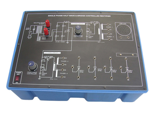
Code:EET3576
Power Electronic Training Board has been designed specifically to single phase half wave & bridge controlled rectifier.
Practical experience on this board carries great educative value for Science and Engineering Students.
Object
- To study the singal phase half wave controlled rectifier & observe the effect of firing angle of wave form.
- To study the bridge controlled rectifier & observe the effect of firing angle of wave form.
Features
The board consists of the following built-in parts:
- 230VA.C. Isolated Transformer, Power 50 watt.
- 9V D.C. at 100mA Zener Regulated Power Supply.
- Two UJT.
- Four SCR's.
- Two Pulse transformer 1:1:1.
- Two Potentiometers for controlling UJT firing angle.
- Bulb 40W, 230VA.C.
- Adequate no. of other Electronic Components.
- Mains ON/OFF switch, Fuse and Jewel light.
- The unit is operative on 230V ±10% at 50Hz A.C. Mains.
- Adequate no. of patch cords stackable 4 mm spring loaded plug length ½ meter.
- Good Quality, reliable terminal/sockets are provided at appropriate places on panel for connections/observation of waveforms.
Other Apparatus Required:
- Dual Trace Cathode Ray Oscilloscope 20 MHz (Unearthed)//with Isolation Transformer for unearthing.


