Educational Motors & Machines


Power Measurement using CT & PT

Code:EET1841

Power Measurement using CT and PT setup is designed to explore the measurement techniques used in electrical meters for measurement of Voltage, Current, Power etc. Current Transformer (CT) and Potential Transformer (PT) are used to sense Current and Voltage respectively from a transmission line. The various parameters that affect the Current and Voltage sensing using CT and PT are primary and secondary winding turns, gauge of wire and type of core. 46607 provides indepth explaination and experimental analysis of various configurations of Current and Voltage measurement using CT and PT

The students can measure the Voltage, Current, Wattage and Power Factor. Digital Voltmeter, Ammeter and Wattmeter are provided on panel to increase accuracy of measurement. The meters have very high accuracy and resolution.

The CT is provided on panel so that students can change the turns in primary winding and measure the corresponding changes in secondary winding and change in measurement. Protection circuit is inbuilt.

Features:

  • High resolution and accurate meters
  • Digital Voltmeter, Ammeter and Wattmeter
  • Internal variable power source
  • Real time appearance of CT with facility to change primary turns
  • Provided with all the accessories including rheostat to perform experiment
  • Designed by considering all the safety precautions
  • Learning material CD
  • 2 Year Warranty

Technical Specifications

  • Mains Supply : 230V ±10%, 50Hz
  • Variac
  • Input : 230V AC
  • Output : 0-270V AC
  • Current Rating : 5A
  • Ammeter (2 nos.)
  • Display Resolution : 0.01A AC
  • Range Min/Max : 0.1/5A
  • Voltmeter (2 nos.)
  • Display Resolution : 1V AC
  • Range Min/Max : 10V/300V
  • Wattmeter
  • Display Resolution : 1W
  • Range Min/Max : 15/1500W
  • Current Transformer
  • CT Ratio : 1:10
  • Secondary Current Rating : 2A
  • Potential Transformer
  • PT1
  • Primary : 230V
  • Secondary : 115V
  • PT Ratio : 1:2
  • PT2
  • Primary : 230V
  • Secondary : 57.5V
  • PT Ratio : 1:4
  • Rheostat : 220W, 2.8A
  • MCB : 2A (SPN)
  • Dimensions (mm) : W 600 x D 350 x H 450
  • Weight : 22kg (approx.)

Scope of Learning

  • To measure high value of AC Current by a low range AC Ammeter and Current Transformer
  • To measure high value of AC Voltage by a low range AC Voltmeter and Potential Transformer
  • To measure Power using CT & PT
  • To study the effect of CT turns ratio in Current measurement
  • To study PT & CT connection in an electric Circuit for measurement

Students can configure primary winding of CT to understand & analyse effect on secondary winding

Meter Demonstrator

Code:EET1846

"Meter Demonstrator" is all in one, training product designed for the students to make them familiar with the variety of analog measuring instrument & their principle . Variable AC & DC supply is provided to observe the response of each type of analog meter.

In modern world of electrical & electronics, it is required to measure many network parameters like current, voltage, energy and power. The analog measuring instruments are broadly classified in three classes: Moving coil, Moving iron & Dynamometer type. The aim of designing the product is to demonstrate the working of all types of analog measuring instruments.

Features:

  • Demonstration of Analog measuring insturments
  • CBT software covering all the experiments
  • Follows all safety standards
  • e-Manual
  • 2 Year Warranty

Technical Specifications

  • Inbuilt Variable AC Supply : 0 to 230V
  • Inbuilt Variable DC Supply : 0 to 6 V ( with load)
  • Meters Used
  • AC Voltmeter (MI) : 0 to 300V
  • DC Voltmeter (MC) : 0 to 10V
  • AC Ammeter (MI) : 0 to 1A
  • DC Ammeter (MC) : 0 to 1A
  • AC Wattmeter (Dynamometer) : 0 to 500W
  • Mains Supply : 230 V ± 10%, 50 Hz
  • Dimensions (in mm) : W 450x D 600 x H 60

Scope of Learning

  • Study the operation of moving coil type instruments
  • Study the operation of moving iron type instruments
  • Study the operation of Dynamometer type instruments

Radial And Ring Main Distribution System

Code:EET1851

Radial and Ring Main Distribution System is specially designed to illustrate the working phenomenon of Distribution System configured as Radial and Ring Main Distribution System. Distribution System is the part of electric power system which connects the high voltage transmission networks to the low voltage consumer service points. Distribution Systems should be designed in a way that Voltage variation at consumer terminals must be maintained with in ±5%.

46609 provides complete learning content to develop Ring and Radial Distribution System manually. The Voltage regulation is studied by performing experiments & comparison. It includes inbuilt DC Variable Supply with adequate protections, precise digital meters are used along with separate sections for Radial and Ring Main Distribution System so that students can understand the significance of these systems in a proper sequence.

Features:

  • Digital 3 nos. DC Voltmeter & 3 nos. DC Ammeter for accurate measurement
  • Separate connection for Radial & Ring Main System
  • Inbuilt DC Variable Supply
  • Isolation Transformer is provided for safe operation
  • Exclusive and attractive designed panel
  • Provided with inbuilt lamp load holders
  • Diagrammatic representation for the ease of connections
  • Learning material CD
  • 2 Year Warranty

Technical Specifications

  • Mains Supply : 230V ± 10%V AC, 50Hz
  • Inbuilt Isolated DC Output Supply
  • Rated Voltage : 0 - 220V ± 10% (Variable)
  • Rated Current : 2A
  • Transformer
  • Rating : 0.5kVA
  • Primary Voltage : 230V
  • Secondary Voltage : 150V
  • Variac
  • Input : 230V
  • Output : 0-270V
  • Current : 2A
  • Digital DC Voltmeter (3 Nos.)
  • Range : 20-500V
  • Display Resolution : 1V
  • Digital DC Ammeter (3 Nos.)
  • Range : 0-5A
  • Display Resolution : 0.01A
  • MCB : 2A (SPN)
  • Dimensions (mm) : W 824 x D 350 x H 624
  • Weight : 42kg (approx.)

Scope of Learning

  • Study of Radial Distribution network
  • Study of Ring Main Distribution network

Single And Three Phase Resistive Load

Code:EET1856

Single and Three Phase Resistive Load is a high wattage resistance network suitable for loading Single Phase and Three Phase supplies and generators. The load banks are used to verify the performance of power sources. However real loads are unpredictable and random in value hence standard loads are used to stimulate environment for testing power sources.

It is designed in robust enclosure. It consists of three banks of switched resistive loads. These three banks can be used with Single Phase and Three Phase Systems. Each bank of resistors is electrically isolated and separate terminals for each phase are provided on panel through a star/delta switch. The user can switch between star and delta very easily.

MCB's are used to change the resistance of the load. The resistive load is equipped with a cooling fan to reduce the temperature. The load is mounted on a trolley to provide facility of easy movement in laboratories.

Features:

  • Suitable for Single and Three Phase Operation
  • Star/Delta Switch for easy conversion
  • Suitable for both static & rotating machines
  • Five selectable load values on each bank
  • Suitable for balanced and unbalanced load Conditions
  • MCBs are used to switch values and provide protection at the same time
  • Provided with cooling fan for heat suppression
  • Designed by considering all the safety standards
  • Equipped with Supply Indication Lamps
  • Provide with trolley for flexible movement
  • Learning material CD
  • 2 Year Warranty

Technical Specifications

  • Single Phase Operation Voltage : 240V AC ±10%, 50Hz
  • Current : 15A
  • Power : 3.5kW
  • Loading steps : 15 MCBs
  • Current rating : 10A (SP)
  • No. of MCBs : 15
  • Three Phase Star Operation Voltage : 415V AC ±10%, 50Hz
  • Current : 5A (per Phase)
  • Power : 3.5kW
  • Loading steps : 5 (per Phase)
  • MCBs (acts as a switch) : 10A (SP)
  • Three Phase Delta Operation Voltage : 415V AC ±10%, 50Hz
  • Current : 15A (per Phase)
  • Power : 10.5kW
  • Loading steps : 5 (per Phase) MCBs
  • Current rating : 10A (SP)
  • No. of MCBs : 15
  • Auxiliary Supply for fan : 230V AC, 50Hz
  • Star/Delta Switch : 415V, 25A
  • MCB : 16A (TPN)
  • Dimensions (mm) : 460 W x 740 D x 590 H
  • Weight : 45kg (approximately)
  • Learning Material :CD (Theory, procedure, reference results, etc), Online (optional)
  • Included Accessories :Learning Material, Patch Cords

Single And Three Phase Inductive Load

Code:EET1861

Single and Three Phase Inductive Load is suitable for loading Single Phase and Three Phase supplies and generators. It consists of robust enclosure that contains three banks of switchable inductive loads. Two terminals for each phase are given which are externally accessible through an inbuilt star delta switch.

All banks of inductors are electrically isolated and separate terminals for each phase are provided on panel through a star/delta switch so that the students can connect as a star or delta load for three-phase circuits. Each bank has a set of switches to bring each inductor into the circuit.

This allows students to study the effects of balanced or unbalanced inductive loads. MCB's are used to change the inductance of the load. Students can connect the loads to experiment circuits using specially designed patch cords on the enclosed front panel. The load is mounted on a trolley to provide facility of easy movement in laboratories.

Features:

  • Suitable for loading Single Phase and Three Phase supply
  • Suitable for both static & rotating machines
  • Star/ Delta switch provides easy switching
  • MCBs are used to switch values and provide protection at the same time
  • Heavy duty wheel for easy movement
  • Suitable for balanced and unbalanced loading conditions
  • Designed by considering all the safety precautions
  • 2 Year Warranty

Technical Specifications

  • Single Phase Operation Voltage : 240V AC ±10%, 50Hz
  • Current : 15A
  • Power : 3.5KVAR
  • Loading steps : 30 MCBs
  • Current rating : 10A (SP)
  • No. of MCBs : 30 Nos.
  • Three Phase Star Operation Voltage : 415V AC ±10%, 50Hz
  • Current : 5A (per Phase)
  • Power : 3.5KVAR
  • Loading steps : 5 (per Phase)
  • MCBs (acts as a switch) : 10A (SP)
  • Three Phase Delta Operation Voltage : 415V AC ±10%, 50Hz
  • Current : 15A (per Phase)
  • Power : 10KVAR
  • Loading steps : 5 (per Phase)
  • MCBs : 10A (SP)
  • Star/Delta Switch : 415V, 25A
  • MCB : 16A (TPN)
  • Dimensions (mm) : 580 W x 750 D x 600 H
  • Weight : 140kg (approximate)
  • Included Accessories:
  • Learning material CD : 1 no.

Single Phase & Three Phase Capacitive Load

Code:EET1866

Single Phase & Three Phase Capacitive Load consists of three banks of switchable capacitors. These three banks can be used with Single Phase & Three Phase Systems. The load banks are used to verify the performance of power source. However real loads are unpredictable and random in value hence standard loads are used and this stimulates environment for testing power sources. The capacitive load bank provides a leading power factor.

46612 is provided with a star and delta switch which facilitates the switching between star and delta connections. The capacitors can be selected in different combinations with the help of MCBs on front panel. The load is mounted on a trolley to provide facility of movement in laboratories.

Features:

  • Suitable for Single and Three Phase Operation
  • Star/Delta switch for easy conversion
  • Ten selectable load values on each bank
  • Suitable for balanced and unbalanced load Conditions
  • MCBs are used to switch loads and provide protection at the same time
  • Provide with trolley for flexible movement
  • Equipped with Supply Indication Lamps
  • Designed by considering all the safety standards
  • Learning material CD
  • 2 Year Warranty

Technical Specifications

  • Mains Supply :230V AC ±10%, 50Hz (Single Phase)
    :415V AC ±10%, 50Hz (Three Phase)
  • Current :4.6A each phase (in Star connection)
    :13A each phase (in Delta connection)
  • Star/Delta Switch : 415V, 32A
  • MCB : 16A (Four Pole) 1 No. 10A (One Pole) 30 Nos.
  • Dimensions (mm) : W 560 x D 350 x H 420
  • Weight : 22kg (approximate)

3-Phase Parameter Measurement

Code:EET1871

a high accuracy 3-phase electrical energy measurement device. It is designed to measure any 3-phase electrical system simultaneously without using individual meters. It is a compact table top unit which includes signal processing required to perform Voltage, Current, Frequency, Active Power, Reactive Power, Apparent Power and Power Factor Measurements. This product is suitable to measure active, reactive, and apparent energy in various 3- phase configurations such as WYE or DELTA services. It is Compatible with both 3-phase/3-wire and 3-phase/4-wire systems. All the parameters measured are displayed simultaneously on a single display unit.

Features:

  • Microcontroller based design for accurate measurement
  • 240 x 128 Graphical LCD Display to view all the parameters
  • Simultaneous display of Three Phase electrical parameters
  • Used with Single Phase / Three Phase supply
  • 2 Year Warranty

Technical Specifications

  • Measurement Connection Type : Input and Output
  • Input Voltage Range(Vr, Vy, Vb) : 3 0 - 2 3 0 V r m s A C , Accuracy ±1%
  • Input Voltage Range(Vry, Vyb,Vbr) : 50 - 450Vrms AC, Accuracy ±1%
  • Input Current Range( Ir, Iy, Ib) : 0.20-10Amp, Accuracy ±1%
  • Frequency : 45 - 55Hz, Accuracy ±0.5Hz
  • Active power : 50 - 5000Watts, Accuracy ±2%
  • Reactive power : 50 - 5000Watts, Accuracy ±2%
  • Apparent power : 50 - 5000Watts, Accuracy ±2%
  • Auxiliary Supply : 230V ±10%, 50Hz
  • Power Factor : 0.30 to 0.99 both Lead and Lag, Accuracy ±2° Electrical

Transformer Oil Testing System

Code:EET1876

Transformer Oil Testing System is used for testing the dielectric strength of insulation oil used in Transformers. Testing is performed to determine the reliability of the oil filled in Transformer. Transformer oil is used in all types of High Voltage Transformers & circuit breakers. This system includes motorized unit for smooth variation of high voltage. Kilovoltmeter is provided for monitoring high voltage. This product also incorporates automatic tripping mechanism for protection against overload.

The equipment consists of two High Voltage Coils having starting winding at earth potential. The High Voltage Transformer is designed for testing Duty only.

Features:

  • Fully motorized high voltage control
  • Break down voltage protection
  • Over current protection
  • Mains & H.T. "ON" & "OFF" Switches
  • Incorporates automatic tripping mechanism
  • Mains and H.T. "ON" indications
  • Test cup with adjustable gap electrode arrangement
  • Equipped with Kilo Voltmeter
  • Designed by considering all the safety standards
  • Learning material CD
  • 2 Year Warranty

Technical Specifications

  • Mains Supply : 230V AC ±10%, 50Hz
  • Single Phase Variac : 230V/ 0-270V
  • High Voltage Source : 80kV, 20mA
  • HV Control Motor
  • Type : Servo
  • RPM : 500 (No Load)
  • Voltmeter : 0 to 100kV
  • Dimensions (mm) : W 600 x D 350 x H 450
  • Weight : 58kg (approximate)

Scope of Learning

  • Study & measurement of Breakdown Voltage (Dielectric Strength) of transformer oil

Transformer Oil Testing System

Code:EET1881

Transformer Oil Testing System is used for testing the dielectric strength of insulation oil used in Transformers. Testing is performed to determine the reliability of the oil filled in Transformer. Transformer oil is used in all types of High Voltage Transformers & circuit breakers. This system includes motorized unit for smooth variation of high voltage. Kilovoltmeter is provided for monitoring high voltage. This product also incorporates automatic tripping mechanism for protection against overload.

The equipment consists of two High Voltage Coils having starting winding at earth potential. The High Voltage Transformer is designed for testing Duty only.

Features:

  • Fully motorized high voltage control
  • Break down voltage protection
  • Over current protection
  • Mains & H.T. "ON" & "OFF" Switches
  • Incorporates automatic tripping mechanism
  • Mains and H.T. "ON" indications
  • Test cup with adjustable gap electrode arrangement
  • Equipped with Kilo Voltmeter
  • Designed by considering all the safety standards
  • Learning material CD
  • 2 Year Warranty

Technical Specifications

  • Mains Supply : 230V AC ±10%, 50Hz
  • Single Phase Variac : 230V/ 0-270V
  • High Voltage Source : 80kV, 20mA
  • HV Control Motor
  • Type : Servo
  • RPM : 500 (No Load)
  • Voltmeter : 0 to 100kV
  • Dimensions (mm) : W 600 x D 350 x H 450
  • Weight : 58kg (approximate)

Scope of Learning

  • Study & measurement of Breakdown Voltage (Dielectric Strength) of transformer oil

MCB And HRC Fuse Testing System

Code:EET1886

MCB (Miniature Circuit Breaker) and HRC (High Rupturing Current Capacity) Fuse Testing System is designed to explain the operating behavior and characteristics of MCB's and HRC fuse. It includes B type MCB, C type MCB and HRC fuse. These are protective devices capable of carrying currents under normal circuit conditions and automatically break the circuit whenever over load or short circuit condition occurs.

46616 provides complete learning contents to demonstrate the internal working of MCB's and HRC fuse. The MCB's are provided in transparent case to visualize the internal architectures. Two precise integrated circuit based Thermometers are provided on bimetal contact of MCB's to analyze the temperature rise and fall.

Digital timer is provided with start and stop facility to study the current versus tripping time characteristics. Inbuilt isolated variable AC Power Supply is provided for safety. The student will learn the difference in various classes of MCB's.

Features:

  • Alphanumeric 16X2 Big Font LCD for better visibility
  • Isolated Power Supply using Transformer
  • Inbuilt variable current injection facility
  • Transparent MCB's to understand internal architecture and its working
  • Inbuilt Timer, Current & Temperature on LCD
  • MCBs are mounted with temperature sensor for current temperature analysis
  • Equipped with supply indication lamp
  • Designed by considering all the safety standards
  • Diagrammatic representation for the ease of connections
  • Learning material CD
  • 2 Year Warranty

Technical Specifications

  • Mains Supply : 0-220V AC ±10%, 50Hz Single Phase Variac
  • Input : 230V
  • Output : 0-270V
  • Current : 10A
  • Single Phase Transformer Rating : 1kVA
  • Input : 230V
  • Output : 230V
  • Experimental Setup MCB's : B type, 6A C type, 2A
  • HRC Fuse : 6A Temperature Sensor (2 Nos.)
  • Type : Mounting type
  • Name : LM35
  • Display Resolution : 0.1°C
  • Mounting : With Brass holder mounted on MCB's
  • Protective Devices : 10A (SPN)
  • Rheostat : 100W / 5A
  • Dimension (mm) : W 600 x D 350 x H 450
  • Weight : 22kg (approx.)

Scope of Learning

  • Study the operating characteristics of Miniature Circuit Breaker B-type 6A. Also draw the Current Time & Temperature-Time characteristics
  • Study the operating characteristics of Miniature Circuit Breaker C-type 2A. Also draw the Current Time & Temperature-Time characteristics
  • Study the operating characteristics of HRC fuse

Over Current Relay Testing System

Code:EET1896

Over Current Relay Testing System is a useful learning product for electrical laboratories. Over Current Relay monitors general balanced overloading and has current time settings. These settings determine the protective schemes. The relay is IDMT type which has different tripping time characteristics with different current conditions. These are classified in accordance with their characteristic curves which indicate the speed of tripping operation. The typical settings for relay is 0.5-2 Amp in 1-10 seconds.

46617 has accurate voltage, current & time measurement. It includes built-in variable supply, digital voltmeter, ammeter, timer. The timer operation is automatic when current is applied to relay. This automatic operation ensures accurate tripping time measurement.

Features:

  • Alphanumeric 16X2 Big Font LCD for better visibility
  • Electromechanical relay to understand internal mechanism and its working
  • Simultaneous display of voltage, current on LCD
  • Inbuilt automatic timer that starts and stop with relay
  • Inbuilt Power Source for relay
  • Diagrammatic representation of relay connection in transmission line
  • Exclusive and attractive design
  • Designed by considering all the safety standards
  • Learning material CD
  • 2 Year Warranty

Technical Specifications

  • Mains Supply : 230V ±10%, 50Hz
  • Rheostat :110W, 5A Single Phase Variac
  • Input : 230V
  • Output : 0 - 270V
  • Current : 0 - 5A
  • Over Current Relay Type : Inverse Time
  • Normal Voltage : 110V AC, 50Hz
  • Current Setting : 0.5A, 0.75A, 1A, 1.25A, 1.50A, 1.75A and 2A
  • CT Secondary : 1A Measurement
  • Voltmeter : 25 - 300V
  • Ammeter : 200mA - 5A
  • Timer : 10mSec - 30min

Scope of Learning

  • To study the IDMT Over Current Relay & its applications
  • To study and use plug setting multiplier
  • To study and use time setting multiplier
  • To study and verify the operating Characteristics of Over Current
  • Relay at various plug & time settings

For understanding the role of relays in real time transmission system a circuit of transmission line is provided from source to distribution with proper placing of all its required components.

Under Voltage & Over Voltage Relay Testing System

Code:EET1901

Under Voltage & Over Voltage Relay Training System is intended for advanced practical training in protective devices regarding transmission lines, cables and network sections in power systems lab. A Relay is an electrically operated switch use an electromagnet to operate a switching mechanism mechanically.

Relays protect the power distribution equipment against continuing voltage sags that are detrimental to motors, ballasts, etc. 46618 provides theoretical and practical experience to students by controlling, monitoring and analyzing individual relay settings and tripping characteristics. This product provides detailed representation of power transmission system which helps the students to perform experiments with minimal supervision. It also includes built-in variable supply and fast response graphical LCD display which makes the measurement system very precise.

Features:

  • Alphanumeric 16 x 2 Big Font LCD for better visibility
  • Electromechanical relay to understand internal mechanism and its working
  • Inbuilt Single Phase Variac with isolation
  • Tripping function settings
  • Exclusive and attractive design
  • Diagrammatic representation of relay connection in transmission line
  • Designed by considering all the safety standards
  • Learning material CD
  • 2 Year Warranty

Technical Specifications

  • Mains Supply : 230V ±10%, 50Hz
  • Single Phase Variac
  • Input : 230V
  • Output : 0-270V
  • Current : 0-5A
  • Over Voltage Relay
  • Normal Voltage : 110V AC, 50Hz
  • Voltage Setting :121V, 126.5V, 132V, 143V,137.5V, 148.5V, 154V
  • Contacts : 2 N/O, 1 N/C
  • Under Voltage Relay
  • Normal Voltage : 110V AC, 50Hz
  • Voltage Setting : 44V, 51.3V, 58.6V, 65.9V, 73.2V, 80.5V ,88V
  • Contacts : 1 N/O, 2 N/C
  • Dimensions (mm) : W 830 x D 350 x H 645
  • Weight : 48kg (approx)

Scope of Learning

  • To study the operating performance of Over Voltage Relay with different plug settings
  • To study the operating performance of Under Voltage Relay with different plug settings

For understanding the role of relays in real time transmission system a circuit of transmission line is provided from source to distribution with proper placing of all its required components.

Earth Fault Relay Testing System

Code:EET1906

Earth Fault Relay Testing System is designed to provide exposure of protection device used to prevent faults in electrical circuits due to earth leakage current. The protection of electrical system is required to maintain any device in operation without failure. There are various types of protective devices used in Power Systems. The knowledge of protective devices helps to use them smartly and avoid system breakdown. Earth leakage current gives rise to heat generation and progressive failure of insulation which leads to earth faults & sparks. The Earth Fault Relay detects the leakage current well before they cross threshold limit.

46619 provides complete learning platform related with the connection of Earth Fault Relay in transmission line and testing of Earth Fault Relay. After experimenting with 7094 the students will be able to use Earth Fault Relay in Power Systems.

Features:

  • Inbuilt variable source
  • Big font LCD display for better visibility
  • Isolation transformer is provided for safe operation
  • Exclusive and rugged designed panel
  • Designed by considering all the safety precautions
  • Diagrammatic representation for the ease of connections
  • Learning material CD
  • 2 Year Warranty

Technical Specifications

  • Mains Supply : 230V±10%V AC, 50Hz Variac
  • Input : 230V
  • Output : 0-270V
  • Current : 0-2A
  • Isolation Transformer Rating : 1kVA
  • Primary Voltage : 0-230V
  • Secondary Volatge : 0-230V
  • Earth Fault Relay Type : Electromechanical Inverse
  • Time Normal Voltage : 110V AC, 50Hz
  • Plug Setting : 0.5A, 0.75A, 1.0A, 1.25A, 1.50A, 1.75A and 2A
  • Rheostat : 110W, 5A
  • Display Measurement Unit
  • Design Technology : AVR RISC Microcontroller
  • Voltmeter : 25 - 300V
  • Measurement Method : Direct ADC interface
  • Display Resolution : 1V
  • Ammeter : 0.2 - 5A
  • Measurement Method : CT based ADC interface
  • Display Resolution : 0.01A
  • Timer Range : 10mSec - 30min
  • Operation : Automatic with relay start operating
  • LCD Specification
  • No. of lines : 2
  • No. of Characters in each line : 16
  • MCB : 6A (SPN)
  • Dimensions (mm) : W 830 x D 355 x H 630
  • Weight : 52kg (approximate)

Scope of Learning

  • TTo study and verify the operating characteristics of Earth Fault Relay with different plug setting
  • To study connection of Earth Fault Relay in transmission line
  • To study testing of Earth Fault Relay

For understanding the role of relays in real time transmission system a circuit of transmission line is provided from source to distribution with proper placing of all its required components.

Differential Relay Testing System

Code:EET1911

Differential Relay Testing System is a versatile product for electrical laboratories. Various type of relays are used as protection devices in combination with circuit breaker in electrical system. The Different Relay operates due to differential current flowing in the circuit. When current between two sections vary from a known and permissible value, the relay gets tripped and protects the connected device.

The Differential Relay requires two current sources for its operating & testing. For this, two current injection units are provided with the system. The current of both the injection units are displayed on LCD with the differential current to perform the experiment with higher stability & accuracy. The students can understand the working of differential relay by measuring the operating characteristics. They can also learn the connection of this protection device in the electrical circuit.

Features:

  • Alphanumeric 16X2 Big Font LCD for better visibility
  • Electromechanical relay to understand internal mechanism and its working
  • Inbuilt Single Phase Variac with isolation
  • Two variable current injection units
  • Tripping function settings
  • Exclusive and attractive design
  • Diagrammatic representation of relay connection in transmission line
  • Designed by considering all the safety standards
  • Learning material CD
  • 2 Year Warranty

Technical Specifications

  • Mains Supply : 230V AC ±10%, 50Hz
  • Single Phase Variac
  • Input : 230V AC
  • Output : 0 - 270V AC
  • Current : 2A
  • Single Phase Transformer
  • Input : 230V AC
  • Output : 24V AC
  • Current : 3A
  • Dimensions (mm) : W 830 x D 350 x H 645
  • Weight : 62kg (approximate)

Scope of Learning

  • To study and verify the operating characteristics of Differential Relay with different plug setting
  • To study the connection of Differential Relay in electrical circuit

For understanding the role of relays in real time transmission system here a circuit of transmission line is provided from source to distribution with proper placing of all its require components

Three Phase Low Voltage Power Supply

Code:EET1916

Three Phase Low Voltage Power Supply is an elite training system for the electrical laboratories. The 46621 is a three phase low voltage supply that provides 18V of low voltage which is highly safe. This system is valuable in understanding the basic concepts of Three phase circuits

Features:

  • Low Cost
  • Provided with two nos. synchronized three phase output
  • Easy to Operate
  • Designed by considering all the safety standards
  • Eqipped with supply indicators
  • Learning material CD
  • 2 Year Warranty

Technical Specifications

  • Mains Supply : Three Phase
  • 415V ±10%, 50Hz
  • Outputs : 18V Phase Voltage
  • 28V ±10% Line Voltage 50Hz
  • MCB : 10A
  • Dimension (mm) : W 262 x D 316 x H 130
  • Weight : 8kg (approximate)

DC Shunt Machines

Code:EET1921

DC Machines have been the running horse for the Industry since 100 Years, Shunt motors have been the most used due to their very simple speed control, Ruggedness & High Torque capabilities.This Model is the Industrial/Educational model suitable for demonstrating to students the complete know of the Basics, Components, Starting methods, Wear & Tear & Maintenance of these motors packaged in small rating.Students can make connections of their own with the help of the terminations provided for study of features viz Starting methods,Speed control, Speed-Torque, Effects of Field voltage, Effects of Armature voltage, Motor/Generator operation.

Technical Specs :

  • Power ratings available : 350W / 750W / 1KW /2 KW / 3KW/ 5KW
  • Voltage Input: 220V DC
  • Excitation : 220V DC
  • Armature : 220V DC
  • RPM: 1500 / 3000 RPM
  • Single / Double shaft extension, SPDP, IP23, IC01, B3, Class-B, S1, Solid Yoke

List Of Experiments :

  • Behavior of Resistance Cut off method of starting
  • Behavior of Voltage control method of starting
  • Speed Control & Over speed operations
  • Load test & No load test of machine
  • Speed-Torque Analysis
  • Voltage-Speed Analysis
  • Efficiency Analysis
  • Analysis of Commutation
  • Cold Resistance & Hot Resistance
  • Motor Operation parameters
  • Generator Operation parameters
  • Basic Overhauling Know how.

DC Series Machines

Code:EET1926

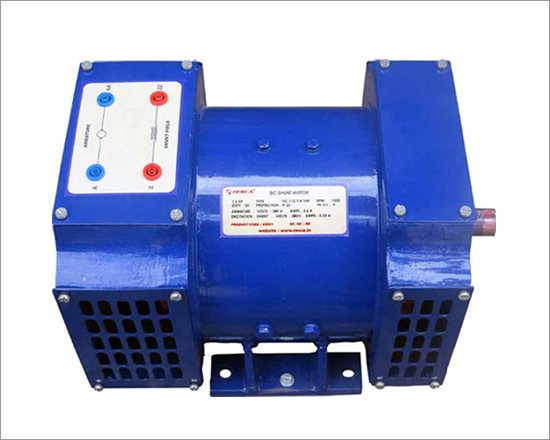
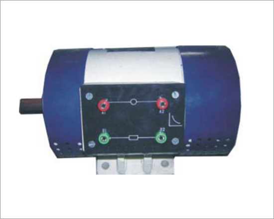
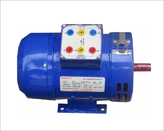
DC Machines have been the running horse for the Industry since 100 Years, Where ever Heavy Torque is required Series motors are the option, these motors need load to start, these motors have the tractive effect & are even named as Traction motors, applications like railways, material handling machines use such motors.

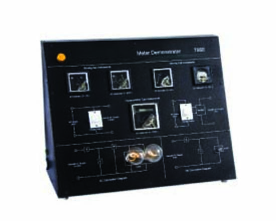
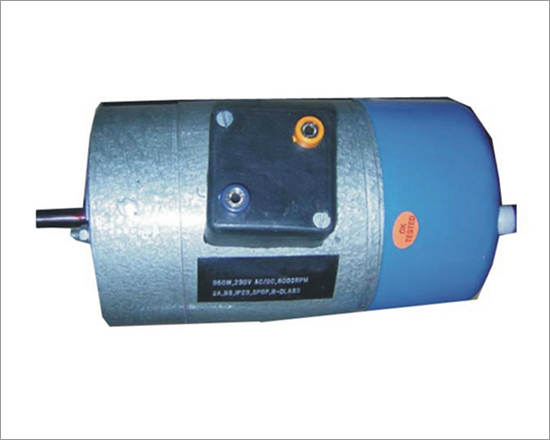
This Model is the Industrial/Educational model suitable for demonstrating to tudents the complete know of the Basics, Components, Starting methods, Wear & Tear & maintenance of these motors packaged in small rating.Students can make connnections of their own with the help of the terminations provided for study of features viz starting methods,Speed control, Speed-Torque, Effects of Armature voltage,Behaviour with Load, Motor/Generator operation.

Technical Specs :

  • Power ratings available : 350W / 750W / 1KW /2 KW / 3KW/ 5KW
  • Voltage Input: 220V DC
  • Armature : 220V DC
  • RPM: 1500 / 3000 RPM
  • Single / Double shaft extension, SPDP, IP23, IC01, B3, Class-B, S1,Solid yoke

List Of Experiments :

  • Behavior of Resistance Cut off method of starting
  • Behavior of Voltage control method of starting
  • Speed Control
  • Load test & No load test of machine
  • Speed-Torque Analysis
  • Voltage-Speed Analysis
  • Efficiency Analysis
  • Analysis of Commutation
  • Cold Resistance & Hot Resistance
  • Motor Operation parameters
  • Generator Operation parameters
  • Basic Overhauling Know how

DC Compound Machines

Code:EET1931

DC Machines have been the running horse for the Industry since 100 Years, Compound motors are one of these types. This Model is the Industrial/Educational model suitable for demonstrating to students the complete know of the Basics, Components, Starting methods, Wear & Tear & Maintenance of these motors packaged in small rating. Students can make connections of their own with the help of the terminations provided for study of features viz Starting methods, Speed control, Speed-Torque, Effects of Field voltage, Effects of Armature voltage, Over compound, Under compound, Motor/Generator operation.

Technical Specs :

  • Power ratings available : 350W / 750W / 1KW /2 KW / 3KW/ 5KW
  • Voltage Input: 220V DC
  • Excitation : 220V DC
  • Armature : 220V DC
  • RPM: 1500 / 3000 RPM
  • Single / Double shaft extension, SPDP, IP23, IC01, B3, Class-B, S1, Solid yoke

List Of Experiments :

  • Behavior of Resistance Cut off method of starting
  • Behavior of Voltage control method of starting
  • Speed Control & Over speed operations
  • Load test & No load test of machine
  • Speed-Torque Analysis
  • Voltage-Speed Analysis
  • Efficiency Analysis
  • Over Compound & Under Compound Effects
  • Analysis of Commutation
  • Cold Resistance & Hot Resistance
  • Motor Operation parameters
  • Generator Operation parameters
  • Basic Overhauling Know how

3Phase AC Squirrel Cage Induction Motor

Code:EET1936

With the availability of 3Phase power becoming common, the use of 3Phase AC Squirrel cage motor became very common & today it holds 90% of the total market share. The simplicity in operation with the 3phase voltages & immediate torque made it a very common motor. This Model is the Industrial/Educational model suitable for demonstrating to students the complete know of the Basics, Components, Starting methods, Wear & Tear & Maintenance of these motors packaged in small rating. Students can make connections of their own with the help of the terminations provided for study of features viz Starting methods, Speed control, Speed-Torque, Effect of Phase angle, Study of Cogging/Crawling, Effects of Single phasing, Effect of voltage imbalance operation, Blocked rotor test.

Technical Specs :

  • Power ratings available : 350W / 750W / 1KW /2 KW / 3KW/ 5KW
  • Voltage Input: 440V AC 50hz
  • RPM: 1440 / 2880 RPM
  • Single / Double shaft extension, TEFC, IP44, IC01, B3, Class-B, S1, Casting body.

List Of Experiments :

  • Starting by DOL Starter
  • Starting by Star-Delta Starter
  • Starting by reduced voltage starter
  • Speed Control by VVVF method
  • Load test & No load test of machine
  • Speed-Torque Analysis
  • Voltage-Speed Analysis
  • Speed reversal
  • Efficiency Analysis
  • Blocked rotor test
  • Cold Resistance & Hot Resistance
  • Motor Operation parameters
  • Basic Overhauling Know how

1Ph AC Squirrel Induction Motor Cap. Start

Code:EET1941

With the availability of 3 Phase power becoming common, the use of 3 Phase AC Squirrel cage motor became very common & demand increased for motors with single phase power, as the current in single phase is a concern, hence motors upto 3Hp have been made In Single phase power with the same Induction design principle. The issue of Starting of the motor with Single phase was tackled by providing Capacitor for creating phase difference. The simplicity in operation & immediate torque made it a common motor for single phase power. This Model is the Industrial/Educational model suitable for demonstrating to students the complete know of the Basics, Components, Starting methods, Wear & Tear & Maintenance of these motors packaged in small rating. Students can make connections of their own with the help of the terminations provided for study of features viz Starting methods, Speed-Torque, Effect of Phase angle, Study of Cogging/Crawling, Effect of reduced voltage, Blocked rotor test.

Technical Specs :

  • Power ratings available : 350W / 750W / 1KW / 1.5KW
  • Voltage Input: 230V AC 50hz
  • RPM: 1440 / 2880 RPM
  • Single / Double shaft extension, TEFC, IP44, IC01, B3, Class-B, S1, Casting/Sheet metal body

List Of Experiments :

  • Starting by DOL Starter
  • Starting by reduced voltage starter.
  • Load test & No load test of machine
  • Speed-Torque Analysis
  • Voltage-Speed Analysis
  • Speed reversal
  • Efficiency Analysis
  • Blocked rotor test
  • Cold Resistance & Hot Resistance
  • Motor Operation parameters
  • Basic Overhauling Know how

AC Repulsion Motor

Code:EET1946

With the availability of 3Phase power becoming common, the use of 3 Phase AC Squirrel cage motor became very common & demand increased for motors with single phase power, as the current in single phase is a concern, hence motors upto 3 Hp have been made In Single phase power with the same Induction design principle. The issue of Starting of the motor with Single phase was tackled by providing Capacitor for creating phase difference. The simplicity in operation & immediate torque made it a common motor for single phase power. This Model is the Industrial/Educational model suitable for demonstrating to students the complete know of the Basics, Components, Starting methods, Wear & Tear & Maintenance of these motors packaged in small rating. Students can make connections of their own with the help of the terminations provided for study of features viz Starting methods, Speed-Torque, Effect of Phase angle, Study of Cogging/Crawling, Effect of reduced voltage, Blocked rotor test.

Technical Specs :

  • Power ratings available : 350W / 750W / 1KW / 1.5KW (Pl Specify)
  • Voltage Input: 230V AC 50hz
  • RPM: 1440 / 2880 RPM (Please specify RPM before placing order, In general for Educational purpose we are supplying 1440 RPM and for Industrial/Commercial Purpose 2880 RPM)
  • Single / Double shaft extension, TEFC, IP44, IC01, B3, Class-B, S1, Casting/Sheet metal body

List Of Experiments :

  • Starting by DOL Starter
  • Starting by reduced voltage starter.
  • Load test & No load test of machine
  • Speed-Torque Analysis
  • Voltage-Speed Analysis
  • Speed reversal
  • Efficiency Analysis
  • Blocked rotor test
  • Cold Resistance & Hot Resistance
  • Motor Operation parameters
  • Basic Overhauling Know how

Universal Motor

Code:EET1951

Universal motors- as the name suggests are universal because they can run on AC Supply as well as DC Supply, they belong to the family of Single phase motors with the difference that they have wound rotor, commutator & brush as used in dc motors. These motors are for intermittent duty cycles as their rpm is very high and find application in Domestic Mixer grinders & Home applicanes, Industrial use is Switch yards in Power sub stations for spring charging of Circuit breakers.This Model is the Industrial/Educational model suitable for demonstrating to students the complete know of the Basics, Components, Starting methods, Speed-Torque, Wear & Tear & Maintenance of these motors packaged in small rating. Students can make connections of their own with the help of the terminations provided for study of features viz Starting methods, Speed-Torque, Effect of reduced voltage, Blocked rotor test.

Technical Specs :

  • Power ratings available : 350W / 750W
  • Voltage Input: 230V AC 50hz or 230 DC
  • RPM: 6000 / 10000
  • Single / Double shaft extension, SPDP, IP23, IC01, B3, Class-B, Short time duty, Solid yoke.

List Of Experiments :

  • Starting by AC DOL Starter
  • Starting by reduced AC voltage starter.
  • Starting by DC Starter
  • Speed control by DC SCR Drive
  • Load test & No load test of machine
  • Speed-Torque Analysis
  • Efficiency Analysis
  • Blocked rotor test
  • Cold Resistance & Hot Resistance
  • Motor Operation parameters
  • Basic Overhauling Know how
Educational Equipments
Biology Lab Microscopes Physics Lab Chemistry Lab
Lab Glassware Chinaware & Porcelain ware Lab Platinum-ware Lab Plasticware Stands, Racks, Clamps Wooden Racks and Stands Electro-Chemistry Power Supplies Electrical Spares & Supplies Molecular Models Organic Chemistry Set Laboratory Balances
/ Lab Measuring Instruments
Measurement Aids Spatula Lab Rubber Tubing Chemistry Lab Consumables Lab Brushes Hand Tools and Others Gas Tap & Fittings Lab Testing Papers Chemistry Lab Models Chemistry Charts Lab Safety Supplies Thermometers Laboratory Chemicals
Lab Microscopes & Slides Laboratory Glassware Lab Plasticware Mathematics Lab School/College Science Kits Geography & Geology Teaching Equipments Educational Charts Whiteboard & Boards
Lab Measuring Instruments Electronics Lab Engineering Lab Testing Lab (Engineering) Astronomy Lab Equipments Civil Engineering Equipments Civil Engineering Models Scientific Lab Instruments Blood Bank Equipments Educational Charts