Code:EET1441
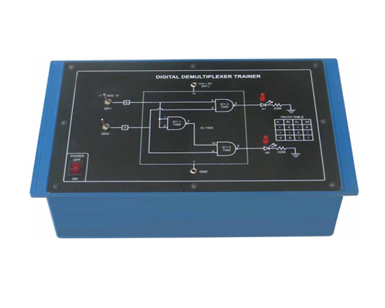
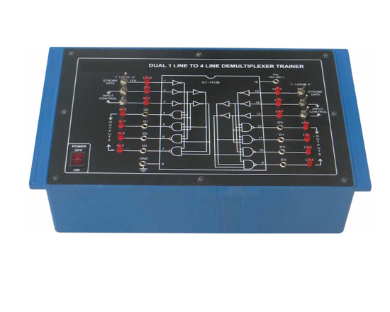
Computer Logic Training Board has been designed specifically to familiarise the operation of a demultiplexer circuits. In digital system the technique of multiplexer and demultiplexers are frequently used to reduce the system cost and to improve the reliability. The unit provides the understanding of two output demultiplexers. This concept can be extended to make the demultiplexers for more complex circuits. The unit is absolutely self contained and requires no other apparatus.
Practical experience on this board carries great educative value for Science and Engineering Students.
Object:
- To study the operation of a Digital Demultiplexer circuit
Features
The unit consists of the following built-in parts :
- +5V D.C. at 50mA, IC Regulated Power Supply internally connected.
- Two switches to set the input and control bits.
- Two LEDs for visual indication of selected line.
- A separate LED provides the indication of logic level of any pin of IC.
- Adequate no. of other electronic components.
- Mains ON/OFF switch, fuse and Neon Indicator are provided.
* The unit is operative on 230V ±10% at 50Hz A.C. Mains.
* Adequate nos. of patch cords stackable from rear both ends 4mm spring loaded plug, length ½ metre
* Good Quality, reliable terminal/sockets are provided at appropriate places on panel for connections / observation of waveforms.
* Strongly supported by detailed Operating Instructions, giving details of Object, Theory, Design procedures, Report Suggestions and Book References.