Digital Electronics Trainer


Logic Training Board on OR/NOR, AND/NAND, NOT/Buffer

Code:EET1331

Computer Logic Training Board has been designed specifically to study simple Logic Functions and Theorems of Boolean Algebra and to compare the truth table with experimental results. This training board offers a new method of training students in the basic theory of digital circuits and make them familiar with basic experiments in digital circuits. The board is absolutely self contained and requires no other apparatus. Practical experience on this board carries great educative value for Science and Engineering Students.

Object:

To study and verify the following :
  • OR/NOR Function.
  • AND/NAND Function.
  • NOT/BUFFER Function.
  • Simple function of several variables.
  • Distributive Law.
  • Commutative Law.
  • Associative Law.
  • De Morgan's Theorem.

Features:

The board consists of the following built-in parts :
  • + 5V D.C. at 500mA, IC Regulated Power Supply internally connected.
  • Two, 3-input NAND gates followed by an inverter to give 3-input AND/NAND gates.
  • Two, 3-input NOR gates followed by an inverter to give 3-input OR/NOR gates.
  • Two, NOT gates followed by another NOT gate to give BUFFER outputs.
  • Switches for logic selection.
  • LEDs for visual indication of status.
  • Adequate no. of other Electronic Components.
  • Mains ON/OFF switch, Fuse and Jewel light.
  • The unit is operative on 230V ±10% at 50Hz A.C. Mains.
  • Adequate no. of patch cords stackable from rear both ends 4mm spring loaded plug length ½ metre.
  • Good Quality, reliable terminal/sockets are provided at appropriate places on panel for connections / observation of waveforms.
  • Strongly supported by detailed Operating Instructions, giving details of Object, Theory, Design procedures, Report Suggestions and Book References.
  • Weight : 3 Kg. (Approx.)
  • Dimension : W 340 x H 110 x D 210

Note: Specifications are subject to change. Order Code can be different from Manufacturer's Model No.

Logic Training Board on Counters & Shift Registers

Code:EET1336

Computer Logic Training Board has been designed specifically for the study of Counters & Shift Registers to make the student familiar with the design and practical aspects of all types of counters, shift registers and their applications in frequency measurements and computers etc.This board with gates and Flip-Flops can be used to construct any type of counter, shift register etc. and the output of each circuit can also be observed in decimal code with the help of decoder and Seven Segment Display. More than 25 experiments can be conducted on this training board. These experiments cover several aspects of computer, input and output devices, memories, arithmetic and control units. Once the student understands these basic circuits, he can combine them in infinite varieties of complex circuits. Practical experience on this board carries great educative value for Science and Engineering Students.


Object:

To design, fabricate and test the following:

(A) COUNTERS

Ripple Counters:

  • 4-Stage binary ripple up-counter.
  • 4-Stage binary ripple down-counter.
  • 4-Stage binary ripple up-down counter.
  • Variable modules ripple counter by direct clearing.
  • 4-Stage decade ripple up-counter by direct clearing.
  • 4-Stage decade ripple down counter by direct clearing.

Synchronous Counters:

  • 4-Stage binary synchronous up-counter with parallel carry.
  • 4-Stage binary synchronous down-counter with parallel carry.
  • 4-Stage binary synchronous up-counter with series carry.
  • 4-Stage binary synchronous down-counter with series carry.
  • 4-Stage binary synchronous up-down counter with parallel carry.
  • 4-Stage synchronous up-down counter with series carry.
  • 4-Stage synchronous decade counter with parallel carry.

Series Parallel Counters:

  • 3-Stage mod-5 series parallel counter.
  • 4-Stage mod-10 series parallel counter.

Ring Counter:

  • Stage ring counter.

Johnson Counters:

  • 4-Stage Johnson or shift counter.
  • Decade counter using 5-stage shift counter.
Miscellaneous Counters:

  • Higher Modules counter by combining two lower modules counter.
  • 2421 BCD counter.
(B) SHIFT REGISTERS

To study the operation of:
  • Serial to parallel converter.
  • Series-in-series output register.
  • Parallel to serial converter.
  • Parallel-in-parallel out register.
  • Right shift and left-shift register.

(C) Application Of Counters.

  • To study the basic principle of frequency measurement.
  • To study the operation of frequency division by counter.
  • To study the principle of Random Access Memory by constructing its basic cell.

Features:

The board consists of the following built-in parts:
  • + 5V D.C. at 1Amp, IC Regulated Power Supply Internally connected.
  • Five, J-K master slave flip-flops with preset and clear arrangement.
  • Six, 2-input NAND gates.
  • Four, 4-input NAND gates.
  • Three, 4-input AND-OR gates.
  • Two inverters (NOT gates).
  • A 4-bit binary counter to demonstrate the basic principles of frequency measurement.
  • A square wave oscillator of frequency 10 Hz, 1 Khz and 10 KHz with coarse and fine variations, demon strata the basic principle of frequency division.
  • Completely programmable panel to make any type Of counter or shift register.
  • Two pulser switches for clear and clock arrangement.
  • One Mono Pulser to give a 1 sec pulse.
  • Three Band switches for various interconnections required in the circuit to provide greater convenience and avoiding wrong connections.
  • Two, 7-segment displays to monitor the output in decimal code.
  • LEDs for visual indication of output status of each flipflop.
  • Adequate no. of other Electronic Components.
  • Mains ON/OFF switch, Fuse and Jewel light.


  • The unit is operative on 230V ±10% at 50Hz A.C. Mains.
  • Adequate no. of patch cords stackable from rear both ends 4mm spring loaded plug length ½ metre.
  • Good Quality, reliable terminal/sockets are provided at appropriate places on panel for connections / observation of waveforms.
  • Strongly supported by detailed Operating Instructions, giving details of Object, Theory, Design procedures, Report Suggestions and Book References.
  • Weight : 6 Kg. (Approx.)
  • Dimension : W 412 x H 150 x D 310
  • Other Apparatus Required
  • Dual Trace Cathode Ray Oscilloscope 20 MHz (Optional).
Note: Specifications are subject to change. Order Code can be different from Manufacturer's Model No.

Analog to Digital Converter (A to D)

Code:EET1341

Computer Logic Training Board has been designed specifically for the study of Analog to Digital Converter. The board is absolutely self contained and requires no other apparatus. Practical experience on this board carries great educative value for Science and Engineering Students.

Object:

  • To study the basic principle on conversion of analog signal to digital signal.
  • To study the working of Digital Voltmeter.

Features:

The board consists of the following built-in parts :
  • + 5V D.C. at 250mA, IC Regulated Power Supply internally connected.
  • - 5V D.C. at 50mA, IC Regulated Power Supply internally connected.
  • + 10V D.C. at 50mA, IC Regulated Power Supply internally connected.
  • 0-15V D.C. at 50mA, continuously variable Power Supply.
  • D.C. Voltmeter, 65mm rectangular dial to read 0-15V.
  • Voltage comparator.
  • Quad 2-input NAND gate.
  • Quad 2-input NOR gate.
  • Qual 2-input AND gate.
  • Dual 4-input AND gate.
  • Quad 2-input EX-OR gate.
  • Three, Hex Buffer/Driver.
  • BCD-to-7 Segment Decoder/Driver.
  • Dual J-K Flip-Flop.
  • 4-Bit Binary Ripple Counter.
  • Timer.
  • Continuous monitoring of analog signals on a voltmeter and of digital signals on 7 segment display.
  • Seven LEDs to display the state of various important points.
  • Two seven segment displays for visual indication of output status.
  • Provision for manual pulses as well as for internal clock.
  • Adequate no. of other Electronic Components.
  • Mains ON/OFF switch, Fuse and Jewel light.


* Adequate no. of patch cords stackable from rear both ends 4mm spring loaded plug length ½ metre.
* Good Quality, reliable terminal/sockets are provided at appropriate places on panel for connections / observation of waveforms.
* Strongly supported by detailed Operating Instructions, giving details of Object, Theory, Design procedures, Report
Suggestions and Book References. * Weight : 3 Kg. (Approx.)
* Dimension : W 340 x H 110 x D 210

Specifications:

  • ANALOG SIGNAL VARIATION : 0 to +15V
  • DIGITAL WORD LENGTH : 4 bits
  • DECODER DISPLAY : 0 to 15
  • (USING 7-SEGMENTS)
  • LEDs INDICATIONS : LED will glow for '1' state and will be OFF for '0' state.
  • SUPPLY REQUIRED : 230V ±10% at 50Hz A.C. Mains.

Digital To Analog Converter (D to A)

Code:EET1346

Computer Logic Training Board has been designed specifically for the study of Digital to Analog Conversion and to make the students familiar with the basic principle & techniques of "Digital to Analog Conversion". Input state switches with storage register are provided to feed the derived digital input and analog output can be read directly on a voltmeter in terms of voltage. The board is absolutely self contained and requires no other apparatus.

Practical experience on this board carries great educative value for Science and Engineering Students.

Object:
To study the basic principle on Digital to Analog Conversion.
Features:

  • The board consists of the following built-in parts :
  • + 5V D.C. at 250mA, IC Regulated Power Supply internally connected.
  • +10V D.C. at 50mA, Power Supply internally connected.
  • -10V D.C. at 50mA, Power Supply internally connected.
  • D.C. Voltmeter, 65mm rectangular dial to read 0-5V.
  • Four, D-type Flip-Flops.
  • Four Level Amplifiers.
  • Continuous monitoring of analog signals on a voltmeter.
  • Four switches for giving binary logic input states.
  • Four LEDs for visual indication of binary logic input status.
  • Adequate no. of other Electronic Components.
  • Mains ON/OFF switch, Fuse and Jewel light.


*Adequate no. of patch cords stackable from rear both ends 4mm spring loaded plug length ½ metre.
*Good Quality, reliable terminal/sockets are provided at appropriate places on panel for connections / observation of waveforms.
*Strongly supported by detailed Operating Instructions, giving details of Object, Theory, Design procedures, Report Suggestions and Book References.
*Weight : 3 Kg. (Approx.)
*Dimension : W 340 x H 110 x D 210

Specifications:

  • DIGITAL INPUT WORD LENGTH : 4 Bits.
  • INPUT STORAGE REGISTER : 4 D type flip-flops.
  • ANALOG SIGNAL VARIATION : 0 to +5V.
  • ANALOG DISPLAY : A voltmeter 0-5V with linear calibration.
  • SUPPLY REQUIRED : 230V ±10% at 50Hz A.C. Mains.
  • D/A MODE : Using Binary weighted ladder network.
Note: Specifications are subject to change. Order Code can be different from Manufacturer's Model No.

Binary to Decimal Encoder

Code:EET1351

Computer Logic Training Board has been designed specifically for the study of Binary to Decimal Encoder. There are arrangements for changing the binary input with the help of a selector switch as well as to feed the unknown 4-bit binary code to read decimal value on seven segment display. The board is absolutely self contained and requires no other apparatus. Practical experience on this board carries great educative value for Science and Engineering Students.

Object:

  • To study the Binary To Decimal Encoder.

Features:
The board consists of the following built-in parts :

  • + 5V D.C. at 50mA, IC Regulated Power Supply internally connected.
  • BCD-to-7-Segment Decoder/Driver.
  • A selector switch to set digits from 0 to 9 with corresponding binary code indicator.
  • A DPDT switch for lamp test of seven segment display.
  • Switch for logic selection.
  • LEDs for visual indication of binary code A,B,C,D.
  • Adequate no. of other Electronic Components.
  • Mains ON/OFF switch, Fuse and Jewel light.


* The unit is operative on 230V ±10% at 50Hz A.C. Mains.
* Adequate no. of patch cords stackable from rear both ends 4mm spring loaded plug length ½ metre.
* Good Quality, reliable terminal/sockets are provided at appropriate places on panel for connections / observation of waveforms.
* Strongly supported by detailed Operating Instructions, giving details of Object, Theory, Design procedures, Report Suggestions and Book References.
* Weight : 3 Kg. (Approx.)
* Dimension : W 340 x H 110 x D 210 Specifications:

  • INPUT WORD LENGTH : 4- Bit
  • SEVEN SEGMENT DISPLAY : 0 TO 9
  • LED INDICATION : LED will glow for '1' state and will be OFF for '0' state.
Note: Specifications are subject to change. Order Code can be different from Manufacturer's Model No.

Digital IC Trainer

Code:EET1356

Computer Logic Training Board has been designed specifically for the study of Digital IC Circuits. The board is designed to train students of Engineering Colleges & Polytechnic Laboratories, in Digital IC circuits. Digital IC Trainer is a completely self contained, most versatile, sophisticated and economical. The board is absolutely self contained and requires no other apparatus.

Practical experience on this board carries great educative value for Science and Engineering Students.

Features:

  • Fully self sufficient with IC Regulated 5V at 1Amp. Power Supply, input logic switches, clock generator, mono pulser.
  • LED logic indicators, 3 digit Seven Segment Displays and provision to take-out output for monitoring.
  • Sockets for ICs, reliable connections using excellent quality sockets.
  • Wiring of all types of experiments become simple and less time consuming.
  • Adequate no. of other Electronic Components.
  • The unit is operative on 230V ±10% at 50Hz A.C. Mains.
  • Adequate no. of patch cords stackable from rear both ends 2mm spring loaded plug length ½ metre.
  • Strongly supported by detailed Operating Instructions, giving details of Object, Theory, Design procedures, Report Suggesti tons and Book References. Two copies each with the trainer board.


* Weight : 8 Kg. (Approx.)
* Dimension : W 412 x H 150 x D 310

Specifications:

  • + 5V D.C. at 1Amp, IC Regulated Power Supply.
  • Eight, two position toggle switches prewired to give binary logic input states.
  • Eight, LED logic indicators with transistor drivers.
  • 3 digit Seven Segment Displays with decoder driver.
  • Clock :- 1 Hz, 1 kHz and 1 MHz.
  • Single pulse from mono pulser.
  • IC Bases :-
    - 16 Pin DIP/ZIF : 3 Nos
    - 28 Pin DIP/ZIF : 1 Nos

Boolean Algebra Trainer

Code:EET1361

Computer Logic Training Board has been designed specifically on Boolean Algebra to study the Boolean Algebraic theorems and verification of the same. By using the clearly marked built-in logic gates, students can implement logic circuits for verification of Boolean Algebraic theorems. The board is absolutely self contained and requires no other apparatus.

Practical experience on this board carries great educative value for Science and Engineering Students.

Object:

To study the following Boolean Algebraic theorems and verification of the same.
  • Single variable theorems.
  • More than one variable theorems.
  • Demorgan's theorems.

Features:

The board consists of the following built-in parts :
  • + 5V D.C. at 100mA, IC Regulated Power Supply.
  • Four NOT gates.
  • Three, 3-input AND gates.
  • Three, 3-input OR gates.
  • Three switches for giving binary logic input states.
  • Two LEDs, driven by LED driver circuit for visual indication of output.
  • Adequate no. of other Electronic Components.
  • Mains ON/OFF switch, Fuse and Jewel light.


* The unit is operative on 230V ±10% at 50Hz A.C. Mains.
* Adequate no. of patch cords stackable from rear both ends 4mm spring loaded plug length ½ metre.
* Good Quality, reliable terminal/sockets are provided at appropriate places on panel for connections / observation of waveforms.
* Strongly supported by detailed Operating Instructions, giving details of Object, Theory, Design procedures, Report Suggestions and Book References.

Study of OR, AND, NAND Gates (using NAND Gate To Make OR, NOR, NOT, AND & EX-OR Gates)

Code:EET1366

Computer Logic Training Board has been designed specifically to study OR, AND, NOT, EX-OR & NAND logic gates and to verify the truth table of various logic functions by using universal NAND gates. The board is absolutely self contained and requires no other apparatus.

Practical experience on this board carries great educative value for Science and Engineering Students.

Object

  • To Study the OR, AND & NAND logic gates and to verify the truth tables.
  • To make various logic functions (OR, NOR, NOT, AND & EX-OR gates) by using NAND gates and verify their truth tables.

Features

The board consists of the following built-in parts :
  • + 5V D.C. at 100mA, IC Regulated Power Supply internally connected.
  • Four, 2-input NAND gates.
  • 2-input OR gate.
  • 2-input AND gate.
  • Two switches for giving binary logic input states.
  • Two LEDs, driven by LED driver circuit for visual indication of output.
  • Adequate no. of other Electronic Components.
  • Mains ON/OFF switch, Fuse and Jewel light.


  • The unit is operative on 230V ±10% at 50Hz A.C. Mains.
  • Adequate no. of patch cords stackable from rear both ends 4mm spring loaded plug length ½ metre.
  • Good Quality, reliable terminal/sockets are provided at appropriate places on panel for connections / observation of waveforms.
  • Strongly supported by detailed Operating Instructions, giving details of Object, Theory, Design procedures, Report Suggestions and Book References.
  • Weight : 3 Kg. (Approx.).
  • Dimension : W 340 x H 110 x D 210
Note: Specifications are subject to change. Order Code can be different from Manufacturer's Model No.

Study Of OR, AND, NOT Logic Gates (using Discrete Components) with TTL IC's

Code:EET1371

Computer Logic Training Board has been designed specifically to study OR, AND, NOT, EX-OR & NAND logic gates and to verify the truth table of various logic functions by using universal NAND gates. The board is absolutely self contained and requires no other apparatus.

Practical experience on this board carries great educative value for Science and Engineering Students.

Object

  • To Study the OR, AND & NAND logic gates and to verify the truth tables.
  • To make various logic functions (OR, NOR, NOT, AND & EX-OR gates) by using NAND gates and verify their truth tables.

Features

The board consists of the following built-in parts :
  • + 5V D.C. at 100mA, IC Regulated Power Supply internally connected.
  • Four, 2-input NAND gates.
  • 2-input OR gate.
  • 2-input AND gate.
  • Two switches for giving binary logic input states.
  • Two LEDs, driven by LED driver circuit for visual indication of output.
  • Adequate no. of other Electronic Components.
  • Mains ON/OFF switch, Fuse and Jewel light.


  • The unit is operative on 230V ±10% at 50Hz A.C. Mains.
  • Adequate no. of patch cords stackable from rear both ends 4mm spring loaded plug length ½ metre.
  • Good Quality, reliable terminal/sockets are provided at appropriate places on panel for connections / observation of waveforms.
  • Strongly supported by detailed Operating Instructions, giving details of Object, Theory, Design procedures, Report Suggestions and Book References.
  • Weight : 3 Kg. (Approx.).
  • Dimension : W 340 x H 110 x D 210
Note: Specifications are subject to change. Order Code can be different from Manufacturer's Model No.

To Study The Characteristics and Operation of a Programmable Counter

Code:EET1376

Computer Logic Training Board has been designed specifically for the study & Operation of Programmable Counter to give students an idea about Programmable Counters and different modes of the same. The output of counter can be observed in decimal code with the help of seven segment displays. The board is absolutely self contained and requires no other apparatus.

Practical experience on this board carries great educative value for Science and Engineering Students.

Object:

  • To study the Programmable Counter in up-mode and carry pulse.,
  • To study the Programmable Counter in down-mode and borrow pulse.
  • To study the presettable mode of the Programmable Counter.

Features:

The board consists of the following built-in parts :
  • +5V D.C. at 100mA, IC Regulated Power Supply internally connected.
  • Programmable Counter IC 74193.
  • Decoder Circuit.
  • Two seven segment displays with decoder circuit to display the output in decimal.
  • One Pulser switch for clock.
  • Two press switches for clear & load.
  • Switches for logic selection.
  • Adequate no. of other Electronic Components.
  • Mains ON/OFF switch, Fuse and Jewel light.


* The unit is operative on 230V ±10% at 50Hz A.C. Mains.
* Adequate no. of patch cords stackable from rear both ends 4mm spring loaded plug length ½ metre.
* Good Quality, reliable terminal/sockets are provided at appropriate places on panel for connections / observation of waveforms.
* Strongly supported by detailed Operating Instructions, giving details of Object, Theory, Design procedures, Report Suggestions and Book References.

Study of Universal Logic Gates &Applications

Code:EET1381

Computer Logic Training Board has been designed specifically to study Universal Logic Gates and Applications. This Training Board is designed to verify the truth table of various logic functions, to prove De-morgan's theorem, Half adder and Full adder by using universal logic gates. The board is absolutely self contained and requires no other apparatus.

Practical experience on this board carries great educative value for Science and Engineering Students.

Object:

  • To study the operation and characteristics of a TTL NAND / NOR gate.
  • To prove the De-morgan's Theorem by using NOR & NAND gates.
  • To perform various logic functions using NOR and NAND gates i.e. OR, AND, NOT, NOR, NAND, Exclusive OR (EX-OR), Half adder and Full adder.

Features:

The board consists of the following built-in parts :
  • +5V D.C. at 100mA, IC Regulated Power Supply internally connected.
  • Ten, 2-input NAND gates.
  • Sixteen, 2-input NOR gates.
  • Switches for logic selection.
  • LEDs for visual indication of status.
  • Adequate no. of other Electronic Components.
  • Mains ON/OFF switch, Fuse and Jewel light.


* The unit is operative on 230V ±10% at 50Hz A.C. Mains.
* Adequate no. of patch cords stackable from rear both ends 4mm spring loaded plug length ½ metre.
* Good Quality, reliable terminal/sockets are provided at appropriate places on panel for connections / observation of waveforms.
* Strongly supported by detailed Operating Instructions, giving details of Object, Theory, Design procedures, Report Suggestions and Book References.

Study Of Various Decoders Using ICs

Code:EET1386

Computer Logic Training Board has been designed specifically for the study of various Decoders using ICs to give students an idea about decoders. The outputs of BCD to decimal decoder are observed with the help of logic level indicators, LEDs & outputs of BCD to seven segment decoder are observed by using seven segment display. The board is absolutely self contained and requires no other apparatus.

Practical experience on this board carries great educative value for Science and Engineering Students.

Object:

  • To study the operations of a BCD to decimal decoder.
  • To demonstrate the operations of BCD to seven segment decoder/Driver.

Features:

The board consists of the following built-in parts :
  • +5V D.C. at 100mA, IC Regulated Power Supply of internally connected.
  • BCD to Decimal Decoder.
  • BCD to Seven segment decoder/driver.
  • Four switches to provide BCD data inputs.
  • Two switches to control LT (Lamp Test) and RBI (Ripple Blanking Input).
  • Ten Logic level indicator LEDs & one seven segment display with decoder circuit to display the outputs.
  • Adequate no. of other Electronic Components.
  • Mains ON/OFF switch, Fuse and Jewel light.


* The unit is operative on 230V ±10% at 50Hz A.C. Mains.
* Adequate no. of patch cords stackable from rear both ends 4mm spring loaded plug length ½ metre.
* Good Quality, reliable terminal/sockets are provided at appropriate places on panel for connections / observation of waveforms.
* Strongly supported by detailed Operating Instructions, giving details of Object, Theory, Design procedures, Report Suggestions and Book References.

Study of Various Types of Flip - Flops

Code:EET1391

Computer Logic Training Board on Flip-Flops has been specifically designed to give students an idea about Flip- Flops and to study different types of Flip-Flops. The output of the Flip-Flops can be observed with the help of logic level indicators (LEDs), which are provided on the panel. The board is absolutely self contained and requires no other apparatus. Practical experience on this board carries great educative value for Science and Engineering Students.

Object:

To construct the following Flip-Flops and study their characteristics :
  • R.S. Flip-Flop without clock.
  • R.S. Flip-Flop with clock.
  • D Flip-Flop.
  • J-K Flip-Flop.
  • T Flip-Flop.
  • Master Slave J-K Flip-Flop.

Features

The board consists of the following built-in parts:
  • +5V D.C. at 100mA, IC regulated power supply.
  • Four, 2-input NAND gates.
  • Four, 3-input NAND gates.
  • One inverter (NOT gate).
  • Four LEDs with driver circuit to observe the output of flip-flops.
  • A pulser to provide the pulses manually for triggering.
  • Adequate no. of other Electronic Components.
  • Mains ON/OFF switch, Fuse and Jewel light.


  • The unit is operative on 230V ±10% at 50Hz A.C. Mains.
  • Adequate nos. of patch cords stackable from rear both ends 4mm spring loaded plug, length ½ metre
  • Good Quality, reliable terminal/sockets are provided at appropriate places on panel for connections / observation of waveforms.
  • Strongly supported by detailed Operating Instructions, giving details of Object, Theory, Design procedures, Report Suggestions and Book References.
  • Weight : 3 Kg. (Approx.).
  • Dimension : W 340 x H 110 x D 210

Note: Specifications are subject to change. Order Code can be different from Manufacturer's Model No.

Study of Left and Right Shift Registers & Ring Counter

Code:EET1396

Computer Logic Training Board has been designed specifically for the study of Left & Right Shift Registers & Ring Counter. This Training Board makes the student familiar about the working, practical aspect and design of the same by using inverter & J-K flip-flops. The board is absolutely self contained and requires no other apparatus.

Practical experience on this board carries great educative value for Science and Engineering Students. Object:

  • To study right shift register.
  • To study left shift register.
  • To study ring counter.

Features:

The board consists of the following built-in parts :
  • +5V D.C. at 100mA, IC Regulated Power Supply.
  • Two dual J-K Flip-Flop with preset & clear arrangement.
  • One inverter (NOT gate).
  • One press switch for clear & one pulser switch for the clock.
  • Four switches to preset the Flip-Flops.
  • LEDs for visual indication of output of each flip-flop.
  • Adequate no. of other Electronic Components.
  • Mains ON/OFF switch, Fuse and Jewel light.


* The unit is operative on 230V ±10% at 50Hz A.C. Mains.
* Adequate nos. of patch cords stackable from rear both ends 4mm spring loaded plug, length ½ metre
* Good Quality, reliable terminal/sockets are provided at appropriate places on panel for connections / observation of waveforms.
* Strongly supported by detailed Operating Instructions, giving details of Object, Theory, Design procedures, Report Suggestions and Book References.

8-Bit Analog to Digital (A/D) Converter (Based on ADC 0800)

Code:EET1401

Computer Logic Training Board has been designed specifically for the Study of 8-Bit Analog to Digital Converter. This Training Board gives a deep understanding of the conversion of Analog signal into Digital signal using IC ADC 0800, which is based on Successive approximation method of Conversion.

Practical experience on this board carries great educative value for Science and Engineering Students.

Object:

  • To Study Conversion of Analog signal to 8-bit Digital signal using IC ADC 0800.

Features:

The board consists of the following built-in parts :
  • ± 5V D.C. at 50mA, IC regulated power supply internally connected.
  • Timer IC 555.
  • A to D convertor IC ADC 0800.
  • Buffer IC 74240.
  • LEDs for visual indication of status.
  • Adequate no. of Electronic Components.
  • Mains ON/OFF switch, Fuse and Jewel light.


  • The unit is operative on 230V ±10% at 50Hz A.C. Mains.
  • Good Quality, reliable terminal/sockets are provided at appropriate places on panel for connections / observation of waveforms.
  • Strongly supported by detailed Operating Instructions, giving details of Object, Theory, Design procedures, Report Suggestions and Book References.
  • Weight : 3 Kg. (Approx.).
  • Dimension : W 340 x H 110 x D 210
  • Other Apparatus Required:
  • Digital multimeter 3¾ digit Order Code - 16901

8-Bit Multiplying Digital to Analog (D/A) Converter (Based on AD1408)

Code:EET1406

Computer Logic Training Board has been designed specifically for the study of 8-Bit Multiplying D/A Converter. This Training Board gives a better understanding of the conversion of digital signal in to an equivalent analog signal using IC AD1408.

Practical experience on this board carries great educative value for Science and Engineering Students.

Object:

  • To Study 8-Bit Multiplying Digital to Analog Converter with 8-Bit Input Digital Signals and Analog output signal representing the product of Inputs and Reference source.

Features:

The board consists of the following built-in parts :
  • ±15V D.C. at 50mA, IC regulated power supply internally connected.
  • +5V D.C. at 50mA, IC regulated power supply internally connected.
  • OP-Amp IC 741.
  • 8-Bit D to A converter IC AD1408.
  • Voltage Regulator IC 723.
  • SPDT switches for logic selection/Input Data.
  • LEDs for visual indication of status/Binary Data Input.
  • Adequate no. of Electronic Components.
  • Mains ON/OFF switch, Fuse and Jewel light.


  • The unit is operative on 230V ±10% at 50Hz A.C. Mains.
  • Good Quality, reliable terminal/sockets are provided at appropriate places on panel for connections / observation of waveforms/ voltages.
  • Strongly supported by detailed Operating Instructions, giving details of Object, Theory, Design procedures, Report Suggestions and Book References.
  • Weight : 3 Kg. (Approx.).
  • Dimension : W 340 x H 110 x D 210
  • Other Apparatus Required:
  • Digital multimeter 3¾ digit Order Code - 16901
Note: Specifications are subject to change. Order Code can be different from Manufacturer's Model No.

Presettable Counter

Code:EET1411

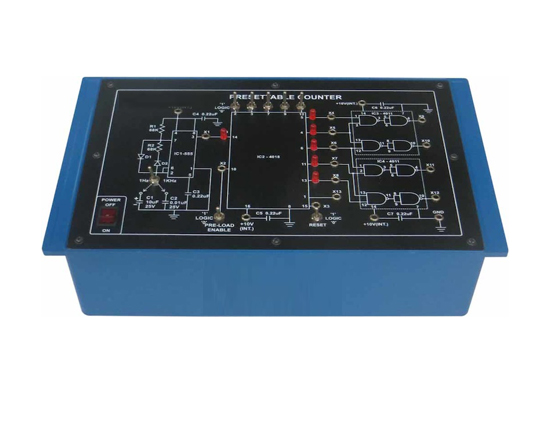
Computer Logic Training Board has been designed specifically for the study of Presettable Counter. This Training Board gives a better understanding of 5-bit counting, starting from a preset initial number and frequency division of clock input by factors of 2, 3, 4, 5, 6, 7, 8, 9 & 10.

Practical experience on this board carries great educative value for Science and Engineering Students. Object:

  • To study beginning of counting for a Preset initial number.
  • To study divide by N programmable counter to give gating pulse of desired duration.

Features:

The board consists of the following built-in parts :
  • + 10V D.C. at 50mA, IC regulated power supply internally connected.
  • Timer 555 IC.
  • Presettable Counter IC 4018.
  • Two NAND GATE ICs 4011.
  • SPDT switches for logic selection.
  • LEDs for visual indication of status.
  • Adequate no. of Electronic Components.
  • Mains ON/OFF switch, Fuse and Jewel light.


* The unit is operative on 230V ±10% at 50Hz A.C. Mains.
* Adequate nos. of patch cords stackable from rear both ends 2mm spring loaded plug, length ½ metre.
* Good Quality, reliable terminal/sockets are provided at appropriate places on panel for connections / observation of waveforms.
* Strongly supported by detailed Operating Instructions, giving details of Object, Theory, Design procedures, Report Suggestions and Book References.

Other Apparatus Required:

  • Frequency Counter 6 digit Order Code - 16915
  • Dual Trace Cathode Ray Oscilloscope 20MHz.

Digital Multiplexer (8-Bit)

Code:EET1416

Computer Logic Training Board has been designed specifically for the study of Digital Multiplexer. This Training Board gives a better understanding of the phenomena of multiplexing with eight input signals and one multiplexed output using three control signals. The board is absolutely self contained and requires no other apparatus.

Practical experience on this board carries great educative value for Science and Engineering Students.

Object:

  • To Study 8-bit Digital Multiplexer with 8 inputs & one multiplexed output using IC 74151.

Features:

The board consists of the following built-in parts :
  • + 5V D.C. at 50mA , IC regulated power supply internally connected.
  • Multiplexer IC 74151.
  • LEDs for visual indication of status.
  • SPDT switches for logic selection.
  • Adequate no. of Electronic Components.
  • Mains ON/OFF switch, Fuse and Jewel light.


  • The unit is operative on 230V ±10% at 50Hz A.C. Mains.
  • Good Quality, reliable terminal/sockets are provided at appropriate places on panel for connections / observation of waveforms.
  • Strongly supported by detailed Operating Instructions, giving details of Object, Theory, Design procedures, Report Suggestions and Book References.
  • Weight : 3 Kg. (Approx).
  • Dimension : W 340 x H 110 x D 210

  • Note: Specifications are subject to change. Order Code can be different from Manufacturer's Model No.

8 Line Demultiplexer (digital)

Code:EET1421

Computer Logic Training Board has been designed specifically for the study of 1:8 Line Demultiplexer. This Training Board gives a better understanding of the phenomena of demultiplexing with one input demultiplexed to eight outputs using three control inputs (Address). Practical experience on this board carries great educative value for Science and Engineering Students.

Object:

  • To Study 8-bit 1:8 Line Demultiplexer using IC 74138.

Features:

The board consists of the following built-in parts :
  • + 5V DC at 50mA, IC regulated power supply internally connected.
  • Demultiplexer IC 74138.
  • Timer IC 555.
  • SPDT switches for logic selection.
  • LEDs for visual indication of status.
  • Adequate no. of Electronic Components.
  • Mains ON/OFF switch, Fuse and Jewel light.


  • The unit is operative on 230V ±10% at 50Hz A.C. Mains.
  • Good Quality, reliable terminal/sockets are provided at appropriate places on panel for connections / observation of wave forms.
  • Strongly supported by detailed Operating Instructions, giving details of Object, Theory, Design procedures, Report Suggestions and Book References.
  • Weight : 3 Kg. (Approx).
  • Dimension : W 340 x H 110 x D 210

Other Apparatus Required

  • Dual Trace Cathode Ray Oscilloscope 20MHz

Universal Shift Register

Code:EET1426

Computer Logic Training Board has been designed specifically for the study of Universal Shift Register. This Training Board gives a better understanding of the concepts of shifting data IN and OUT of a 4-bit register in different modes. The board is absolutely self contained and requires no other apparatus.

Practical experience on this board carries great educative value for Science and Engineering Students.

Object:

To Study the shifting of 4 bit data using IC 74LS194 in the following modes:
  • Serial Left IN - Serial Left OUT.
  • Serial Left IN - Serial Right OUT.
  • Serial Right IN - Serial Left OUT.
  • Serial Right IN - Serial Right OUT.
  • Serial Left IN - Parallel OUT.
  • Serial Right IN - Parallel OUT.
  • Parallel IN - Serial Left OUT.
  • Parallel IN - Serial Right OUT.
  • Parallel IN - Serial OUT.

Features:

The board consists of the following built-in parts :
  • + 5V D.C. at 50mA, IC regulated power supply internally connected.
  • Universal Register IC 74LS194.
  • Transparent latch IC 74LS373.
  • JK Flip-flop IC 74LS74
  • AND GATE IC 7411.
  • NAND GATE IC 7400.
  • Adequate no. of Electronic Components.
  • Mains ON/OFF switch, Fuse and Jewel light.


* The unit is operative on 230V ±10% at 50Hz A.C. Mains.
* Good Quality, reliable terminal/sockets are provided at appropriate places on panel for connections / observation of waveforms.
* Strongly supported by detailed Operating Instructions, giving details of Object, Theory, Design procedures, Report Suggestions and Book References.
Educational Equipments
Biology Lab Microscopes Physics Lab Chemistry Lab
Lab Glassware Chinaware & Porcelain ware Lab Platinum-ware Lab Plasticware Stands, Racks, Clamps Wooden Racks and Stands Electro-Chemistry Power Supplies Electrical Spares & Supplies Molecular Models Organic Chemistry Set Laboratory Balances
/ Lab Measuring Instruments
Measurement Aids Spatula Lab Rubber Tubing Chemistry Lab Consumables Lab Brushes Hand Tools and Others Gas Tap & Fittings Lab Testing Papers Chemistry Lab Models Chemistry Charts Lab Safety Supplies Thermometers Laboratory Chemicals
Lab Microscopes & Slides Laboratory Glassware Lab Plasticware Mathematics Lab School/College Science Kits Geography & Geology Teaching Equipments Educational Charts Whiteboard & Boards
Lab Measuring Instruments Electronics Lab Engineering Lab Testing Lab (Engineering) Astronomy Lab Equipments Civil Engineering Equipments Civil Engineering Models Scientific Lab Instruments Blood Bank Equipments Educational Charts