Consumer Electronics Trainers


Bernoulli's Theorem Demonstrator

Code:EET1186

Bernoulli's Theorem Demonstrator facilitates the students and the industrial professionals to explore the fundamentals of "Bernoulli's Theorem" in Fluid Mechanics. It states that, in a steady flow the sum of all forms of mechanical energy (kinetic, potential and pressure energy) in a fluid along a streamline is the same at all points on that streamline. It consists of classical venture of clear acrylic. A series of wall tapping allows measurement of static pressure distribution of convergent duct, while a total head tube is provide at the centre of throat. These tapping are connected to a bank of manometer tube. This unit has been designed with Hydraulic Bench to study the characteristic flow through convergent and divergent section. During the experiment, the water fed to the venture and the flow rate can be control by the gate valve at the outlet of venture. The venture is used to demonstrate the flow rate measurement and to determine the co-efficient of discharge.

  • Self contained system
  • Simple representation of concept
  • Direct measurement of static head
  • Seven pressure tapings along with tubes
  • Requires minimal installation
  • Robust and transparent Venturimeter
  • All tanks are rust proof

Technical Specifications

  • Test Section (Venture)
    - Throat Diameter - 12mm,
    - Upstream Diameter - 33 mm
    - Upstream Taper - 10°
    - Downstream Taper - 17°
    - MOC - Acrylic (Transparent)
  • Manometer : 0 to 300 mm, Seven Tubes (Flexible & Transparent)
  • Reservoir Tank : 503 ' 300 310 mm, Capacity - 40 Liters
  • Overhead Tank : 191 195 450 mm, Capacity - 16 Liters
  • Measuring Tank : 290 300 251 mm, Capacity - 23 Liters
  • Pump : 72 LPM, 0.5 HP, 230 V, 50 Hz Level Indicator : 20 cm
  • (Body mounted type)

Scope of Learning

  • To verify Bernoulli's Theorem.
  • To observe (visually) types of flow (laminar or turbulent) and calculation of Reynolds Number

SMD Technology Kit

Code:EET1191

Today's electronic gadgets & equipments are miniaturized with each passing day. In the industry it has largely replaced the previous construction method of fitting components with wire leads into holes in the circuit board (also called through-hole technology) and it has totally revolutionized the manufacturing process. Surface Mount Technology (SMT) is method for constructing electronic circuits in which the components are mounted directly onto the surface of printed circuit boards (PCBs). Electronics devices so made are called Surface Mount Devices or MSDs. An SMD component is usually smaller then its leaded counterpart because it has no leads or smaller leads. It may have short pins or leads of various styles, flat contacts, a matrix of balls (BGAs), or terminations on the body of the component (passives), unlike discrete components, SMD components have a huge vareity of packages (size). SMD Technology will be the order of the day for the electronics industry in the coming years. SMD offers Small size, consequent High Packing Density, High Reliability & Improved High Frequency performance. SMD Technology Kit to keep you in pace with the technology revolution. The user is familiarized from components their packages to soldering practice.SMD Technology Kit Contains:


  • SMD Identification Board The user is familiarized with different SMD Components -Resistors, Capacitors, Inductors, Diodes, Transistors & IC's packages.
  • Proto BOARDS Proto BOARDS are special PCB's with readymade solder pads for various SMD components & IC's, which makes the soldering much easy. It includes Through Hole, SO, SOP, Chip Scale package Proto BOARDS.
  • SMD Soldering Jig
  • SMD Soldering Iron AVariable Temperature Controlled Soldering Iron is supplied with lead.
  • SMD components SMD components are supplied for Solder practice. Resistors , Capacitors, Diodes , Transistors
  • Tweezers: Holding & placing of SMD components.

List of Accessories :

  • SMD Identification Board with manual 1 no.
  • Proto BOARDS 2 nos each
    - Discrete Surface Mount
    - SOP
    - SO
    - Through Holes
    - Chip Scale
  • SMD Soldering Jig 1 no.
  • SMD Soldering Iron 1 no.
  • SMD components Resistors , Capacitors, Diodes , Transistors 10 no. each
  • Tweezers 2 no.
  • Manual 1 no.

Spectrum Analyzer Application Demonstration Trainer

Code:EET1196

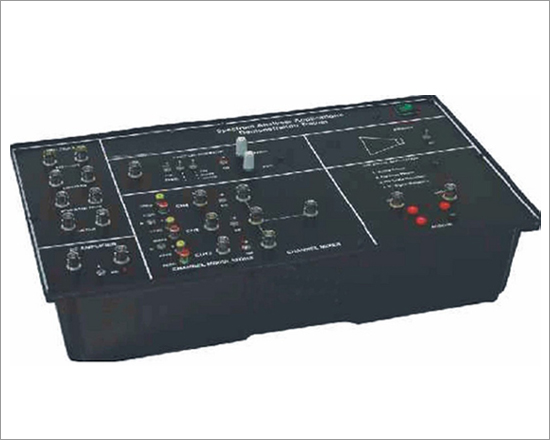
The Trainer has been specially designed for learning how to use a Spectrum Analyzer for Frequency and Level Measurements and Tracking Generator applications like HF Filters and Amplifier Response, Channel Modulation, Mixers, study of Mobile and Cordless signals and study of Harmonics in sine, square & triangular waves. TV & FM transmitted signals can be analyzed on Spectrum Analyzer using this Trainer and audio output can be heard on the speaker mounted inside the trainer. Technical Specifications
Housing :

  • All experiments are housed in a single attractive box which is self contained, ready to use having built- in DC power supplies.

Experiments :

  • The manual describes 18 experiments that can be performed with this trainer and Spectrum Analyzer.

Application I
Filter Responses : Four filters, very precisely designed for checking filter responses on Spectrum Analyzer.
Types of filters are :

  • Low pass Filter (Cut off 115 MHz approx.)
  • High pass Filter (Cut off 100 MHz approx.)
  • Wide Band pass Filter (Cut off 25 MHz - 280 MHz approx.)
  • Notch Filter or narrow band reject filter (Cut off 95 MHz-160 MHz approx.)

Application II
  • DC Amplifier Frequency Response : A well designed DC
  • Amplifier having 3 dB cut off bandwidth of approx. 130 MHz

Application III
  • Harmonic Display & Analysis : A Function Generator of frequency range approx. 40 KHz - 400 KHz (Low) and 200 KHz - 2 MHz (High) having sine, square,& triangular output with frequency variation and output level variation(Max.1 V ). Any one output can be given to Spectrum pp Analyzer for harmonic display.

Application IV
  • Cable TV application : Three channel modulator (channel 4, channel 8, & channel 12) & one mixer is cascaded. Channel modulations have Audio and Video inputs. The output of modulators and mixer can be seen on Spectrum Analyzer.

Application V
Live signal Application :
Four types of signal can be seen on Spectrum Analyzer
  • Mobile phone forward and reverse link frequency
  • Cordless phone Transmitting and receiving frequencies
  • FM Radio Reception (Demodulated Audio output)
  • TV signal Reception (Demodulated Audio output)

Demodulated output from Spectrum analyzer is given to the built- in speaker via Audio amplifier. A built in telescopic Antenna is provided with Spectrum Analyzer for catching signals
  • Power Supply : 220 V ±10%, 50 Hz / 60 Hz on request
  • Power Consumption : 2 VA(approx.)
  • Weight : 4.5 Kg (approx.)
  • Dimensions (mm) : W 440 × D 265 × H 155

Included accessories :
  • Telescopic Antenna 1 No.
  • Patch Cord
  • BNC Cable 2 Nos.
  • Phono jack connector
  • Manual
  • Mains Cord

DSO Demonstration Trainer

Code:EET1201

An ideal trainer for studying the applications of a Digital Storage Oscilloscope. The applications demonstrated forms part of the electronics lab. All experiments are housed in a single attractive box which is self contained, ready to use having built- in DC power supplies.

  • Single shot : Switching transient of a push to on switch is demonstrated
  • Slow Motion: Charging and discharging of an electrolytic capacitor
  • Medical : ECG Simulated wave with pulse rate adjustment
  • Low repetition rate : Sine wave generator of low frequency
  • Mechanical : Relay bouncing and turn ON time
  • Audio : MIC Testing with variable gain audio amplifier

Application I

  • Single shot : Switching transient of a push to on switch is demonstrated.

Application II

  • SlowMotion : Charging and discharging of an electrolytic capacitor.

Application III

  • Medical : ECG Simulated wave with pulse rate adjustment

Application IV

  • Low repetition rate: Sine wave generator of low frequency.

Application V

  • Mechanical : Relay bouncing and turn ON time.

Application VI
Audio : MIC Testing with variable gain audio amplifier.

  • Power Supply : 230 V ±10 %, 50 Hz / 60 Hz on request
  • Power Consumption : 2 VA(approx.)
  • Dimensions (mm) : W 340 × D 240 × D 105

Included accessories :
  • 2mm Patch Cord 1 No.
  • Micro phone , Manual and Mains Cord
  • The manual describes 10 experiments that can be performed with this trainer and Digital Storage Oscilloscope.

Stereo Tape Recorder Trainer

Code:EET1206

Stereo Tape Recorder Trainer is ideal equipment to teach the operation of stereo recording and stereo cassette playing function. The comprehensive study of Tape record and Mechanism unit technique is described in the operating manual. One of the main features of this trainer is fault simulation. The fault created in the trainer in no way damages the trainer.

Technical Specifications

  • Amplifier Type : Class B amplifier
  • Audio Power Output : 14 W (7 W × 2 channels )
  • Frequency Response : 100 Hz to 8 KHz
  • Tape Speed : 4.75 cm / sec
  • Erase Head : Fix magnet
  • RP Head : YBBT 62 (Stereo
  • Mechanism : R X 39
  • Motor : CCW 12 V DC
  • Circuit Block :
    • Pre amplifier CH-L & CH-R
    • Bass - Treble CH-L & CH-R
    • Output amplifier CH-L & CH-R
    • Equalization CH-L & CH-R
    • Output level indicator section
    • Power supply section
  • Panel Control :
    • Volume CH-L & CH-R
    • Bass CH-L & CH-R
    • Treble CH-L & CH-R
  • Mechanism Control : Record, Play, Reverse, Forward, Stop, Pause
  • Recording Facility : Condenser Mic and EP socket for feeding external signal
  • PCB Size (mm) : 260 × 230
  • No. of faults : 15
  • No. of Test point : 42
  • Power Supply : 220 V ±10 %, 50 Hz / 60 Hz on request
  • Power Consumption : 8.17 W (approx.)
  • Compact design
  • Fault creation and diagnosis
  • 42 Test Points
  • More than 15 faults can be demonstrated on this trainer
  • No soldering and de-soldering is required to simulate faults
  • The main IC's are provided on socket to provide a facility to check similar IC' and also to create the faults by inserting faulty IC's in the sockets
  • Test points detail with typical voltage and wave forms are provided in the manual
  • In built power supply
  • Two identical mono channels clubbed together to obtain stereo effect through stereo head Both internal and external recording facility available
  • Recording process understood through LED indicator present in equalization section
  • 8P-2W R/P switch mechanism planed widely through 16 nos 1P-2W toggle switches
  • Separate bass/treble section to understand the effect of low frequency as well as high frequency signal

RFID Trainer

Code:EET1211

RFID TRAINER is an excellent learning/ training system for understanding basics, working and application of RFID (Radio Frequency Identification). It comprises of Contactless RFID Reader, 5 Mifare contactless cards, RFID Applications/Demo/Video Software. System works on 13.56 MHz and ISO 14443A read and write support. RFID is an automatic identification technique, storing and retrieving data using RFID tags or transponders. RFID tags (Active or Passive) is stuck into a product, animal or person for identifying using radiowaves. Most RFID tags have 2 parts: Integrated circuit for storing, processing information, modulating/ demodulating a RF signal and Antenna for receiving/ transmission. Applications for RFID includes transport payments, product tracking, animal identification, inventory systems, human implants, libraries etc.

Features:

  • Software for understanding/working on Applications, Demo, Product Videos
  • Contactless RFID Reader at 13.56 MHz with 6cm range
  • Can be used for Active RFID tags (Optional)
  • Read/Write ISO 14443A protocol Mifare 1K memory RFID cards
  • 16 x 2 LCD Display with 89C51 Micro controller
  • On board Breadboard with 840 tie points for designing other applications
  • High Speed Transactions and flexible configurations
  • USB to Serial interface for RFID Reader
  • Parallel Interface for applications
  • Weight : 6 Kg. (Approx.)
  • Dimension : W 412 x H 150 x D310

Specifications:

  • Operating Frequency: 13.56 Mhz
  • Protocol: ISO 14443A and Mifare 1K Tags
  • Antenna/ Modulation: In built Antenna with ASK modulation

Software

  • Software for RFID Contact less card reader with 7 applications
  • Screen Shot Videos for 7 Applications in steps
  • Live Video Demo for the complete RFID training system
  • RFID Introduction


  • Operating Range: Contact less 6 cm
  • Voltage & Current: 5V@80mA for Reader; 5V@200mA for LCD; 12V@1.5A for stepper motor
  • Operating Temperature: -5 to 75 oC
  • Applications

Hardware Based Experiments

  • RFID Seven Segment Interface (Counter).
  • RFID Stepper Motor (Two) Interface.(With Two Stepper Motor)
  • RFID Logic Switch /LED Interface.
  • RFID LCD Interface.
  • RFID Breadboard Interface.

Software Based Experiments

  • Alarm
  • Database
  • Calculator
  • Read/Write Block

Accessories:

  • Mifare RFID cards ---------------------------------------5
  • Software CD ----------------------------------------------4
  • Mains Cord -----------------------------------------------1
  • 25 Pin Parallel Male-Female Cable --------------------1
  • 9 Pin Parallel Male-Female Cable ----------------------1
  • Instruction Manual ---------------------------------------1
  • Patch Cord 2mm to 1mm 35cm Red & Black ---------5 each.
  • Patch Cord 2mm to 1mm 15cm Red & Black ---------5 each.

Elevator Training Set Technical Documents

Code:EET1216

Overview

  • "DLPLC - DT1 elevator training set" is professional PLC control training object which designed for vocational and technical education, higher education, designed for "programmable logic controller technology" and "programmable logic controller principle and its application", "maintenance electrician", "PLC application technology", "PLC principle and application " course in the colleges and universities This device is suitable for PLC (programmable logic controller) learning and application training, students' pre-job training and worker retraining in senior vocational colleges and universities, higher institutions, not only can meet PLC experiment teaching and related courses design and assessment requirements of universities and colleges, vocational schools, but also can be used as engineering and technical personnel training equipment.

The system function

  • The elevator training device is composed of floor, car, stroke limit institutions, call light, car door, control panel, control motor, sensor, actuator, etc. can collect all kinds of signals, such as inner-choose button signal, outer-choose button signal, floor limit signal, elevator threshold signal, can realize the logic control; Be able to do two groups of car elevator and the elevator door switch control, and can combine experiment; Have up and down and open-close door hardware power-off protection function, effectively avoid motor offside operation fault; Through the content of the project, project analysis, project implementation, project summary and ability evaluation, complete the basic skills, professional skills and post skills.

System feature

  • It is composed of the floor, has car, stroke limit institutions, call light, car door, control panel, control motor, sensor, actuator, etc.
  • Electrical aspects is composed of dc reducer motor and sensors, limit switch, light,etc.
  • This system uses the computer simulation modern information technology means, through the operation, simulation, simulation, three training level, solves the professional training theory, experiment, practice and actual application disjointed problem.
  • Configure configuration software, and provide application guidance and application engineering example.
  • Easy to learn: supporting help to learn software material library. Supporting educational software, electronic materials, material database software, project teaching software, industry simulation software, etc. series of teaching software upgrading.
  • Easy to teach: use the project teaching method combining with the teaching case. Supporting higher education publishing
  • multimedia electronic teaching material, multimedia electronic teaching plan production platform and project teaching software, make the teacher's experiment teaching and theoretical teaching easier
  • Protection function: with lifting and on hardware power-off protection function, effectively avoid motor offside operation failure.

Elevator Training Set Technical Documents

Code:EET1221

Overview

  • This set can truly simulate elevator working condition. It can complete lift go up and down, open and close door. The set is composed by working portion, control portion and PC interface. The working porting including various industrial gearing and sensor. It well simulate elevator open closed structure. The control portion have three control method (PLC,MCU and PC)to complete control operation.
  • The set auto un controlled by MCU. Starting control button which on interface panel to control elevator. Additionally, the set can connect with PLC to control elevator. Rotating change-over witch SA1 to change control method (MCU, PLC or PC).
  • This set install PC monitor which can direct monitoring elevator running on PC. This set is composed by aluminium training platform, car platform sill, signal transfer part and building show parts

Parameter

  • Working pressure: DC24V
  • Temperature: -100C ~ 400C; Humidity: £ 90% (250C).
  • Total capacity: £1KVA

Description

  • This set including DC motor, Car platform sill operation section, Digital tube display section, Sensor training section. The system is modular open structure training platform. You can use different brand PLC or add other training modular as required.
  • The elevator Training set is composed by baseboard, on down car platform sill, stroke limited position institution, call indicate light, car gate, control panel, control motor, sensor and transmission gear. It can collect all signal such as inner choose button signal, outer choose button signal, floor spacing signal ,elvator door spacing signal which complete logic control ,control of lift car up and down also elevator open and close. Additionally, Power off protection of the open and close can avoid motor offside operating.
  • This system use PC simulation technic by operating and simulating settled some pratical problems.
  • With configuration software an offer application guidance and application samples.
  • Easy to learn with software, soft teaching materials, material database software and so on.
  • Easy to teach : project and didactic combined .Multi-media and practic software made experiment teaching and theory teaching easy.
  • Protection: Avoid offside Operating by power-off protection.

Training Contents.

  • Open and close control experiment
  • Second floors inside choose up and down,open close control experiment.
  • Thirds floors inside choose up and down control experiment
  • Third floors outer call up and down, open and close control experiment.
  • Third floors elevator comprehensive control experiment
  • PLC control experiment
  • MCU control experiment
  • PC software control expreiment
Main Part List
Item Name Material Quantity Unit
Training Platform Aluminium alloy structure 1 Set
Car platform 1 Set
Floor show Digital tube display 1 Set
Button Blue 1 Set
Car gate Dark Brown Acrylic Sheet 1 Set
Signal change over parts K4 Terminal 1 Set
Connection Cable 1 Set
Control mode transition Switch 1 PC
Testing line 1 Set
Case Procedure CD 1 PC
Instruction Book 1 Set

Elevator Training Set Technical Documents

Code:EET1226

Overview

  • This set can truly simulate elevator working condition. It can complete lift go up and down, open and close door. The set is composed by working portion, control portion and PC interface. The working porting including various industrial gearing and sensor. It well simulate elevator open closed structure. The control portion have three control method (PLC,MCU and PC)to complete control operation.
  • The set auto un controlled by MCU. Starting control button which on interface panel to control elevator. Additionally, the set can connect with PLC to control elevator. Rotating change-over witch SA1 to change control method (MCU, PLC or PC).
  • This set install PC monitor which can direct monitoring elevator running on PC. This set is composed by aluminium training platform, car platform sill, signal transfer part and building show parts

Parameter

  • Working pressure: DC24V
  • Temperature: -100C ~ 400C; Humidity: £ 90% (250C).
  • Total capacity: £1KVA

Description

  • This set including DC motor, Car platform sill operation section, Digital tube display section, Sensor training section. The system is modular open structure training platform. You can use different brand PLC or add other training modular as required.
  • The elevator Training set is composed by baseboard, on down car platform sill, stroke limited position institution, call indicate light, car gate, control panel, control motor, sensor and transmission gear. It can collect all signal such as inner choose button signal, outer choose button signal, floor spacing signal ,elvator door spacing signal which complete logic control ,control of lift car up and down also elevator open and close. Additionally, Power off protection of the open and close can avoid motor offside operating.
  • This system use PC simulation technic by operating and simulating settled some pratical problems.
  • With configuration software an offer application guidance and application samples.
  • Easy to learn with software, soft teaching materials, material database software and so on.
  • Easy to teach : project and didactic combined .Multi-media and practic software made experiment teaching and theory teaching easy.
  • Protection: Avoid offside Operating by power-off protection.

Training Contents.

  • Open and close control experiment
  • Second floors inside choose up and down,open close control experiment.
  • Thirds floors inside choose up and down control experiment
  • Third floors outer call up and down, open and close control experiment.
  • Third floors elevator comprehensive control experiment
  • PLC control experiment
  • MCU control experiment
  • PC software control expreiment
Main Part List
Item Name Material Quantity Unit
Training Platform Aluminium alloy structure 1 Set
Car platform 1 Set
Floor show Digital tube display 1 Set
Button Blue 1 Set
Car gate Dark Brown Acrylic Sheet 1 Set
Signal change over parts K4 Terminal 1 Set
Connection Cable 1 Set
Control mode transition Switch 1 PC
Testing line 1 Set
Case Procedure CD 1 PC
Instruction Book 1 Set

LED Television Trainer

Code:EET1231

10937 Understanding LED Television is a friendly training platform to learn the operation of LED Television receiver. It is demonstrator cum training system specifically designed for the comprehensive practical study on LED TV engineering for the beginners with a basic knowledge of the various electronic building blocks and fundamentals of communication system

This didactic product develops the sense of investigation within the student and familiarises him with repair/design techniques. One of the main features of this training system is fault simulation to educate on actual fault finding, by simulating faults on this platform. The complete block diagram of LED TV system is printed on the mimic. Finally this equipment allows us to do experiments and to observe waveforms/signals/voltages of different sections, which are guided thoroughly by theory and product tutorials to gain indepth knowledge of the system. Scope of Learning:

  • Study the specifications of full HD LED Television
  • Study the block diagram and operating principle of LED TV
  • Study the functions of front panel controls/ keys of LED TV
  • Study the functions of controls on Remote
  • Study of circuit description and functions of different sections
  • Study and observation of waveforms/signals of different sections
  • Study and measurement of voltages of different sections
  • Study of switch faults and troubleshooting in different sections

Features:

  • Superior quality 20-inch full HD LED Color Television/ PC Monitor
  • Manual and Remote control operation
  • PAL/ NTSC video formats
  • Composite video input/ VGA input
  • Complete block diagram of a LED TV system on-board
  • The different circuit sections of LED TV are exposed on a PCB
  • Easy identification of different parts and components of the system at a glance
  • Easy measurement of voltages and observation of waveforms on test points
  • Soldering free fault creation and troubleshooting
  • Online Product Tutorial
  • 1 Year Warranty

Technical Specifications:

Display
  • Display Type : LED, HD
  • Screen Size : 20 Inch (50cm)
  • Display Resolution : 1600 X 900 pixels
  • Contrast Ratio : Mega Contrast Ratio
  • Display Color : 16.7 Million Display Colors
  • Viewing Angle : 170 (H) X 170 (V)
  • Refresh Rate : 50 Hz
  • Video Interface : Video Input/ VGA input
  • Audio Interface : RCA L & R
  • Audio Output Power : 8W X 2
  • Receiving System : PAL BG/I/DK and NTSC
  • Channel Coverage :VHF-2-12; UHF21-69; CATV (X~Z+2, S11S41)
  • Antenna Impedance : 75? Unbalanced
  • Application : Color Television/ PC Monitor Connectivity
  • USB : 1 X USB 2.0 (MPEG, JPEG, MP3)
  • HDMI : Yes (1 X HDMI)
  • Other Connectivity : RF In, AV In. Ypbpr In, VGA In, VGAAudio In, AV out
  • Composite A/V : Yes
  • Component Video : Yes
  • Analog Audio : Yes
  • Test Points : 55 nos
  • Switched Faults : 50 nos
  • Remote Battery : UM-4, "AAA" 1.5V (2 nos)
  • Mains Supply : 110-260V AC ± 10%, 50/60Hz
  • Power Consumption : 35W
  • Weight : 11 Kg (approximately)
  • Dimension : W430 X D252 X H82
  • Included Accessories : Remote, Mains cord, 34 Pin FRC cable, 15 Pin D type cable each 1 no.
Educational Equipments
Biology Lab Microscopes Physics Lab Chemistry Lab
Lab Glassware Chinaware & Porcelain ware Lab Platinum-ware Lab Plasticware Stands, Racks, Clamps Wooden Racks and Stands Electro-Chemistry Power Supplies Electrical Spares & Supplies Molecular Models Organic Chemistry Set Laboratory Balances
/ Lab Measuring Instruments
Measurement Aids Spatula Lab Rubber Tubing Chemistry Lab Consumables Lab Brushes Hand Tools and Others Gas Tap & Fittings Lab Testing Papers Chemistry Lab Models Chemistry Charts Lab Safety Supplies Thermometers Laboratory Chemicals
Lab Microscopes & Slides Laboratory Glassware Lab Plasticware Mathematics Lab School/College Science Kits Geography & Geology Teaching Equipments Educational Charts Whiteboard & Boards
Lab Measuring Instruments Electronics Lab Engineering Lab Testing Lab (Engineering) Astronomy Lab Equipments Civil Engineering Equipments Civil Engineering Models Scientific Lab Instruments Blood Bank Equipments Educational Charts