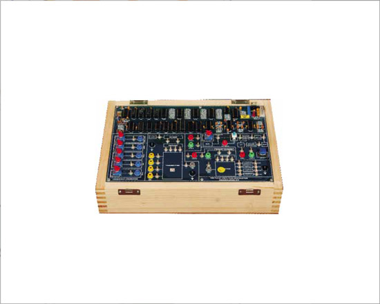
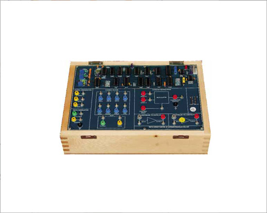
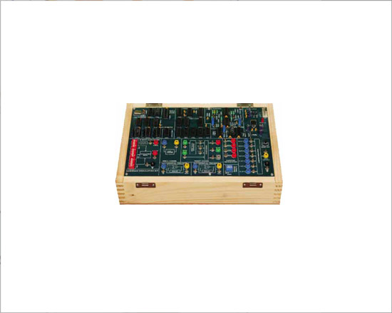
PAM-PPM-PWM Modulation And Demodulation Trainer

Code:EET0881
PAM-PPM-PWM are the basic Pulse Modulation techniques. The trainer provides complete set up to the students for performing experiments on these techniques. They can study Sampling, Pulse Modulation, Demodulation & Signal reconstruction process. Separate circuits are provided for each technique. The Operating Manual provides technology details and procedure to perform the experiments.
Technical Specifications
- Pulse Modulation Techniques :
- Pulse Amplitude Modulation
- Pulse Width Modulation
- Pulse Position Modulation
- On-board Sampling
- Frequencies (Pulse) : 8 KHz, 16 Khz, 32KHz, 64 KHz
- On-board Generator :
- Sinewave : 1 KHz & 2 KHz (Gain Adjustable)
- Squarewave : 1KHz & 2 Khz
- Low Pass Filter : 4Th order BW Filter
- Voice Communication : Voice Link usingdynamic mic & speaker
- AC Amplifier : With Adjustable Gain Control
- DC Output : 0-4 V (Variabl e)
- Switched Faults : 8 Nos.
- Interconnections : 4mm Banana Sockets
- Test Points : 29
- Power Supply : 220 V ±10 %, 50 Hz / 60 Hz on request
- Power Consumption : 3 VA(approx.)
- Dimensions (mm) : W 340 × D 241 × H 105
- Weight : 2.8 Kg (approx.)
- Accessories : Manual, Set of patch cord, Line cord, Microphone, Headphone
Features:
- PAM-PPM-PWM Modulation & Demodulation techniques, using Natural & Flat-top sampling.
- Analog Sample, Sample & Hold and Flat-top outputs.
- Selectable 4 different sampling pulse frequencies on board.
- Input-output and test points provided on board.
- Voice Communication using dynamic microphone & speaker
- On-board Filter and AC Amplifier
- 8 Switched Faults
- Built in DC Power Supply.
Experiments
- PAM using Natural & Flat Top sampling
- Sample, Sample & Hold & Flat-top outputs in PAM
- PPM using DC & AC (sinewave) modulating signals
- Pulse Position Demodulation
- Pulse width Modulation & Demodulation
CDMA Trainer
Code:EET0886
CDMA trainer provides a basic understanding of the concepts behind CDMA and various concepts needed to be considered in case of CDMA system design such as pseudo random bit signal generation,the spreading and despreading of data sequence, Direct Sequence Spread Spectrum (DSSS) generation and decoding , digital modulation and demodulation for BPSK and PWM
Experiments:
- To study theory of CDMA DSSS modulation & Demodulation
- To generate CDMA-DSSS signal
- To demodulate CDMA-DSSS signal using BPSK
- To study pseudo random bit sequence generation.
Technical Specifications
- Power supply requirement 230VAC, 50Hz
- In built regulated power supply
- On board Digital Data signal generator to generate any binary input
- Word length : 8 bit
- Word clock frequency : 240 kHz
- Data format NRZ (Non Return to Zero)
- On board Pseudo Random Bit Signal generator to generate pseudo randombit sequence signal
- Bit length : 15 bits
- Direct sequence spread spectrum (DSSS) generator and decoder
- On board analog signal generator variable upto 3.4khz
- Modulator:
- Binary Phase Shift Keying Modulator
- Pulse Width Modulator
- Demodulator :
- Binary Phase Shift Keying Demodulator
- Pulse Width Demodulator
- Power Supply : 220 V ±10 %, 50 Hz / 60 Hz on request
- Power Consumption : 4 VA (approx.)
QPSK Modulation / Demodulation Trainer
Code:EET0896
Features:
- Clock Generator
- Synchronous clock generator using IC 555
- Frequency of square wave is 200 Khz.
- Carrier Generator
- Provides Four quadri-phase carrier output generated using IC 7490.
-100KHz (0°), 100KHz (90°), 100KHz (180°), 100KHz (270°)
- Data Generator
- Synchronous data generator using IC 74165
- Data stream generated at approx.1Kb/s rate.
- Switch selectable simulated data stream.
- On-board Block features
- QPSK -modulator circuit.
- QPSK -Demodulator.
- Block Description Screen printed on glassy epoxy PCB
- Interconnections
- All interconnections are made using 2mm banana Patch cords
- Test points are provided to analyze signals at various points.
- All ICS are mounted on IC Sockets.
- Bare board Tested Glass Epoxy SMOBC PCB is used.
- In-Built Power Supply of +5V/1.5A, ±12V/250mA with Power ON indication
- Attractive enclosure
- Set of 2mm Patch cords for interconnections.
- User's Manual with sample experiments programs.
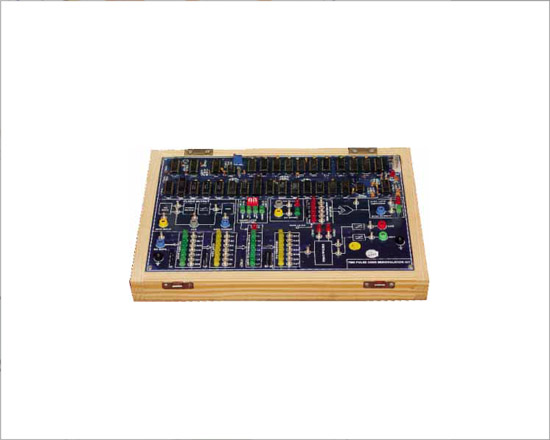
TDM Pulse Amplitude Modulation/Demodulation Trainer
Code:EET0901
Digital Communication Trainer System to under stand various digital Modulation and Demodulation Techniques. Various functional block diagrams are provided on-board for Teaching/Training. This Kits provides with various Test Points to visualize the signals on Oscilloscopes.
Features:
- On-board 250Hz, 500Hz,1KHz, 2Khz Sine-wave generator.
- Sampling rate of 32 KHz/Channel.
- Channel Identification Signal of 8 Khz.
- 4 Nos. of Analog Input Channel for multiplexing & Demultiplexing.
- Clock regeneration at receiver using PLL
- On-board 4th order Butter-worth Low pass filter with cut off frequency of 3.4khz.
- In-Built Power Supply.
List of Experiments:
- Study of Time Division Multiplexing and Demultiplexing using Pulse Amplitude modulation and demodulation.
- Study of TDM Pulse Amplitude modulation and demodulation With Channel Identification Information.
- Study of TDM Pulse Amplitude modulation and demodulation using PLL method.
Specifications:
- Sine Wave Generator
- Provides Sine waveform output of 250Hz, 500Hz, 1 KHz,and 2 KHz.
- Amplitude adjustments possible
- DC Source
- Separate DC source Available.
- Amplitude adjustments possible
- Pulse Generator
- Sampling rate of 32 KHz/channel.
- 8KHz. Channel Identification Signal
- 6.144 MHz. Crystal Controlled Pulse Generator.
- On-board features
- Four Analog Input Channels for Multiplexing/Demultiplexing
- Clock regeneration at receiver using PLL.
- 4th order Butterworth Low pass filter with cut off frequency of 3.4 Khz.
- Block Description Screen printed on glassy epoxy PCB
- Interconnections
- All interconnections are made using 2mm banana Patch cords
- Test points are provided to analyze signals at various points.
- All ICS are mounted on IC Sockets.
- Bare board Tested Glass Epoxy SMOBC PCB is used.
- In-Built Power Supply of +5V/1.5A, ±12V/250mA with Power ON indication
- Attractive enclosure
- Set of 2mm Patch cords for interconnections.
- User's Manual with sample experiments programs.
- 315mm x 245mm x 105mm (L x W x H).
- Weight 3 Kgs.
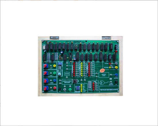
TDM Pulse Code Modulation Trainer
Code:EET0906
Digital Communication Trainer System to under stand various digital Modulation and Demodulation Techniques. Various functional block diagrams are provided on-board for Teaching/Training. This Kits provides with various Test Points to visualize the signals on Oscilloscopes.
Features:
- Internal 500Hz & 1KHz Sine-wave generator.
- Two Nos. of variable Amplitude DC Level.
- 2 Nos. of Analog Input Channels.
- Error Check code option (None, Even, Odd, Hamming)
- None, Even, Odd, Hamming Parity selections.
- Pseudo random sync. code generation.
- 2 Mode of Operation Fast (240 KHz/Channel approx.)& slow (1Hz./channel approx.)
- In-Built Power Supply.
List of Experiments:
- Study of Pulse Code Modulation.
- To study the principles of Analog to Digital and Digital to Analog Conversion
- Study of Pseudo Random Sequences
- Study of Error Check Code Logic:
- None Parity Coding.
- Odd Parity Coding.
- Even Parity Coding.
- Hamming Coding.
- Study of effect of faults in Modulation & Demodulation Techniques
Specifications:
- Sine Wave Generator
- Provides Sine waveform output of 500Hz, 1 KHz.
- Amplitude adjustments possible
- DC Source
- Two Nos. of variable DC source.
- Amplitude adjustments possibleGenerator.
- Mode of Operation
- Fast (240 KHz/Channel approx)
- Slow (1Hz. /channel approx.)
- On-board features
- Two Nos. of Input Channels.
- Pseudo random sync. Code generator for FRAME Synchronization.
- PLL for Bit synchronization.
- Block Description Screen printed on glassy epoxy PCB
- Interconnections
- All interconnections are made using 2mm banana Patch cords
- Test points are provided to analyze signals at various points.
- All ICS are mounted on IC Sockets.
- Bare board Tested Glass Epoxy SMOBC PCB is used.
- In-Built Power Supply of +5V/1.5A, ±12V/250mA with Power ON indication
- Attractive enclosure
- Set of 2mm Patch cords for interconnections.
- User's Manual with sample experiments programs.
- 315mm x 245mm x 105mm (L x W x H).
- Weight 3 Kgs.
TDM Pulse Code Demodulation Trainer
Code:EET0911
Digital Communication Trainer System to under stand various digital Modulation and Demodulation Techniques. Various functional block diagrams are provided on-board for Teaching/Training. This Kits provides with various Test Points to visualize the signals on Oscilloscopes.
Features:
- Single Channel Serial Input.
- Pulse Code Demodulation.
- On-board 4th order Butter-worth Low pass filter with cut off frequency of 3.4khz
- On - b o a r d PL LTe c h n i q u e f o r regeneration.
- Error Check code option (None, Even, Odd, Hamming)
- None, Even, Odd, Hamming Parity selections.
- Pseudo random sync. code generation.
- In-Built Power Supply.
List of Experiments:
- Study of Pulse Code Modulation.
- Study of Error Check Code Logic:
- None Parity Coding.
- Odd Parity Coding.
- Even Parity Coding.
- Hamming Coding.
- Study of Synchronization techniques using PLL.
- Study of effect of faults in Modulation & Demodulation Techniques
Specifications:
- Input Channels
- 2 Channel Time Division Multiplexed Pulse Code Modulation Receiver.
- Mode of Operation
- Fast (240 KHz/Channel approx)
- Slow (1Hz. /channel approx.)
- On-board features
- Pseudo random sync. Code generator for FRAME Synchronization.
- Receiver clock generation using PLL.
- Error Detection of None, Even, Odd, Hamming.
- Error Correction using Hamming Code technique
- None, Even, Odd, Hamming Parity selections
- Two Nos. of 4th order Butterworth Low pass filter with cut off frequency of 3.4 KHz.
- Four Switched Faults for Fault Selection
- Block Description Screen printed on glassy epoxy PCB
- Demodulation Techniques:
- Delta modulation & demodulation.
- Adaptive /CVSD modulation & demodulation.
- Interconnections
- All interconnections are made using 2mm banana Patch cords
- Test points are provided to analyze signals at various points.
- All ICS are mounted on IC Sockets.
- Bare board Tested Glass Epoxy SMOBC PCB is used.
- In-Built Power Supply of +5V/1.5A, ±12V/250mA with Power ON indication
- Attractive enclosure
- Set of 2mm Patch cords for interconnections.
- User's Manual with sample experiments programs.
- 315mm x 245mm x 105mm (L x W x H).
- Weight 3 Kgs.
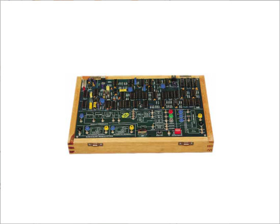
Delta / Adaptive Delta Modulation / Demodulation Trainer
Code:EET0916
Digital Communication Trainer System to under stand various digital Modulation and Demodulation Techniques. Various functional block diagrams are provided on-board for Teaching/Training. This Kits provides with various Test Points to visualize the signals on Oscilloscopes.
Features:
- On-board 250Hz, 500Hz,1KHz, 2Khz Sine-wave generator.
- Sampling rate of 8KHz, 16KHz, 32KHz, 64KHz.
- On-board Compander & Expander.
- On-board Gain integration setting.
- On-board 4th order Butter-worth Low pass filter with cut off frequency of 3.4khz
- In-Built Power Supply.
List of Experiments:
- Study of delta modulation and delta demodulation.
- Study of Slope Overload and Increased Integration Gain in Delta Modulation.
- Study of Adaptive Delta modulation and CVSD.
- Study of companding systems.
- Study Voice modulation and Demodulation (Delta) OPTIONAL.
- Study Voice modulation and Demodulation (CVSD) OPTIONAL.
- Study Voice modulation and Demodulation (Companding) OPTIONAL
Specifications:
- Sine Wave Generator
- Provides Sine waveform output of 250Hz, 500Hz, 1 KHz,and 2 KHz.
- Amplitude of 0 - 4Vp-p
- Amplitude adjustments possible.
- Pulse Generator
- Switch selectable sampling clock of 8KHz, 16KHz, 32 Khz, 64 KHz.
- Crystal Controlled Pulse Generator.
- On-board features
- Unipolar to Bipolar, Integrator for Modulation & Demodulation.
- CVSD Modulator and demodulator
- Input and Output buffer are provided.
- 2nd order Butter-worth Low pass filter with cut off frequency of 3.4 Khz.
- 4th order Butter-worth Low pass filter with cut off frequency of 3.4 Khz
- Compander and Expander are provided.
- Block Description Screen printed on glassy epoxy PCB
- Demodulation Techniques:
- Delta modulation & demodulation.
- Adaptive /CVSD modulation & demodulation.
- Interconnections
- All interconnections are made using 2mm banana Patch cords
- Test points are provided to analyze signals at various points.
- All ICS are mounted on IC Sockets.
- Bare board Tested Glass Epoxy SMOBC PCB is used.
- In-Built Power Supply of +5V/1.5A, ±12V/250mA with Power ON indication
- Attractive enclosure
- Set of 2mm Patch cords for interconnections.
- User's Manual with sample experiments programs.
- 315mm x 245mm x 105mm (L x W x H).
- Weight 3 Kgs.
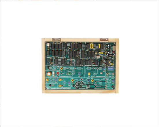
Data Conditioning Trainer
Code:EET0921
Digital Communication Trainer System to under stand various digital Modulation and Demodulation Techniques. Various functional block diagrams are provided on-board for Teaching/Training. This Kits provides with various Test Points to visualize the signals on Oscilloscopes.
Features:
- On-board 1MHz (0°), 1MHz(180°), 2MHz(0°) Carrier Generator.
- On-board Clock and Coding data
- Data format of NRZ-L, NRZ-M, NRZ-S, URZ, AMI, BIO-L, BIO-M, BIO-S. ASK, PSK, FSK Modulator.
- On-board Unipolar to Bipolar and Bipolar to Unipolar conversion.
- In-Built Power Supply.
List of Experiments:
- Study of Data Coding and Decoding Techniques for Nonreturn to Zero Format.
- Study of Data Coding and Decoding Techniques for Phase Encoded Format.
- Study of Data Coding and Decoding Techniques for Return to Zero Format and Multilevel binary format.
- Study of Amplitude Shift Keying Modulation Techniques.
- Study of Frequency Shift Keying Modulation Techniques.
- Study of Phase Shift Keying Modulation Techniques.
Specifications:
- Carrier Generator
- Provides Carrier Sine wave output of 1MHz (0°), 1MHz(180°), 2MHz(0°) .
- Amplitude of 0 - 4Vp-p
- Data Generator
- On-board 8 bit Data Generator for simulation of data
- On-board features
- Carrier Modulation using ASK, PSK, FSK
- Data formats of NRZ-L, NRZ-M, NRZ-S, URZ, Bi-phase-L,Bi-phase-M, Bi-phase-S, AMI.
- On board Carrier Modulation.
- On-board Data Simulator.
- On-board Uni-polar to Bipolar conversion
- On-board Bipolar to Uni-polar conversion
- Block Description Screen printed on glassyepoxy PCB
- Demodulation Techniques:
- ASK, FSK, PSK Demodulation.
- Interconnections
- All interconnections are made using 2mm banana Patch cords
- Test points are provided to analyze signals at various points.
- All ICS are mounted on IC Sockets.
- Bare board Tested Glass Epoxy SMOBC PCB is used.
- In-Built Power Supply of +5V/1.5A, ±12V/250mA with Power ON indication
- Attractive enclosure
- Set of 2mm Patch cords for interconnections.
- User's Manual with sample experiments programs.
- 315mm x 245mm x 105mm (L x W x H).
- Weight 3 Kgs.
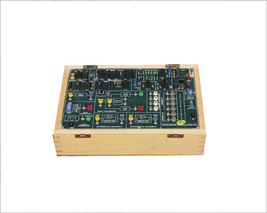
Data Reconditioning Trainer
Code:EET0926
Digital Communication Trainer System to under stand various digital Modulation and Demodulation Techniques. Various functional block diagrams are provided on-board for Teaching/Training. This Kits provides with various Test Points to visualize the signals on Oscilloscopes.
Features:
- Data format of NRZ-L, NRZ-M, NRZ-S,URZ, AMI, BIO-L, BIO-M, BIO-S converted to NRZ-L.
- ASK, PSK, FSK Demodulator.
- In-Built Power Supply.
List of Experiments:
- Study of different Data formats to NRZ-L Format.
- Study of Amplitude Shift Keying Demodulation Techniques.
- Study of Frequency Shift Keying Demodulation Techniques.
- Study of Phase Shift Keying Demodulation Techniques.
Specifications:
- Carrier Demodulation using ASK, PSK, FSK.
- Data formats of NRZ-L, NRZ-M, NRZ-S, URZ, Bi-phase-L, Bi-phase-M, Bi-phase-S, AMI encoded to NRZ-L format.
- Receiver Clock generated by PLL.
- Carrier Demodulation done by
- Rectifier Diode for ASK.
- PLL Detector for FSK.
- Square Loop Detector for PSK.
- Block Description Screen printed on glassy epoxy PCB.
- Demodulation Techniques:
- ASK, FSK, PSK Demodulation.
- Interconnections
- All interconnections are made using 2mm banana Patch cords
- Test points are provided to analyze signals at various points.
- All ICS are mounted on IC Sockets.
- Bare board Tested Glass Epoxy SMOBC PCB is used.
- In-Built Power Supply of +5V/1.5A, ±12V/250mA with Power ON indication
- Attractive enclosure
- Set of 2mm Patch cords for interconnections.
- User's Manual with sample experiments programs.
- 315mm x 245mm x 105mm (L x W x H).
- Weight 3 Kgs.
FDM Trainer
Code:EET0931
List of Experiments:
- Study of Carrier Frequency Generation.
- Study of DSBAM Generation Circuit.
- Study of DSBAM Demodulation Circuit.
- Study of Generation of Frequency Division Multiplexer signal.
- Study of Generation of Frequency Division De-multiplexer signal
Specifications:
- Sine Wave Generator
- Two Nos. of Sine Wave generators Provided.
- Independent Switch selection of 10Hz, 100 Hz, 1 KHz, & 10 KHz.
- Provision for Amplitude adjustments provided.
- Provision for Frequency adjustments provided
- Carrier Generator
- Fixed Sine Wave Generators of 100 KHz and 200 Khz
- On-board features
- Two Nos. of DSB-SC Modulator.
- Summing Amplifier provided
- Two Nos. of Balanced De-modulator.
- Audio input & output amplifier.
- Two 2nd order Butterworth Low pass filter with cut off frequency of 10 Khz.
- Block Description Screen printed on glassy epoxy PCB
- Interconnections
- All interconnections are made using 2mm banana Patch cords
- Test points are provided to analyze signals at various points.
- All ICS are mounted on IC Sockets.
- Bare board Tested Glass Epoxy SMOBC PCB is used.
- In-Built Power Supply of +5V/1.5A, ±12V/250mA with Power ON indication
- Attractive enclosure
- Set of 2mm Patch cords for interconnections.
- User's Manual with sample experiments programs.
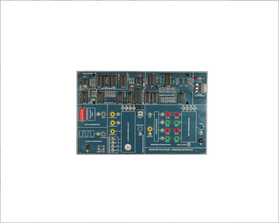
BPSK / DEPSK / DPSK Modulation / Demodulation Trainer
Code:EET0936
Advance Digital Communication Trainer System that helps one under stand various Digital Modulation and Demodulation Techniques. Various functional block diagrams are provided on-board as an aid for Teaching/Training. These Kits are provided with various Test Points to visualize the signals on Oscilloscopes.
Features:
- Onboard synchronized 500 KHz Sine-wave generator.
- Differential Encoding type Data Format.
- On-board crystal controlled Pulse Generator.
- On board 8 bit Data Simulator.
- Block Description screen printed on PCB
- In-Built Power Supply.
List of Experiments:
- Principles of advance digital modulation techniques.
- Differential Encoding of Data.
- Binary Phase Shift Keying Modulation / Demodulation technique.
- Differential Phase Shift Keying Modulation / Demodulation technique.
- Differentially Encoded Phase Shift Keying Modulation / Demodulation technique.
- Effect of Switch Faults.
Specifications:
- Carrier Sine Wave Generator
- Provides synchronized Sine waveform output of 500KHz(0 deg.), 500KHz(180 deg.)
- Clock And Data Generator
- 8 bit variable NRZ-L pattern generated depending on the position of the 8-dit Data Switch provided.
- Clock Frequency is of 250 Khz.
- Data Format (Coding)
- Non Return to Zero-Level (NRZ-L)
- Differential Encoded NRZ-L.
- Carrier Demodulation Techniques
- BPSK modulation
- DPSK modulation
- DEPSK modulation
- On-board features
- Square Looping Technique used in Demodulation section
- Switch Faults are provided on board to study different effects on circuit
- Block Description Screen printed on glassy epoxy PCB
- Interconnections
- All interconnections are made using 2mm banana Patch cords
- Test points are provided to analyze signals at various points.
- All ICS are mounted on IC Sockets.
- Bare board Tested Glass Epoxy SMOBC PCB is used.
- In-Built Power Supply of +5V/1.5A, ±12V/250mA with Power ON indication
- Attractive enclosure
- Set of 2mm Patch cords for interconnections.
- User's Manual with sample experiments programs.
QPSK / DQPSK Modulation Trainer
Code:EET0941
Advance Digital Communication Trainer System that helps one under stand various Digital Modulation and Demodulation Techniques. Various functional block diagrams are provided on-board as an aid for Teaching/Training. These Kits are provided with various Test Points to visualize the signals on Oscilloscopes.
Features:
- Onboard synchronized 500 KHz Sine-wave generator.
- Dibit Pair, Differential Encoding type Data Format.
- On-board crystal controlled Pulse Generator.
- On board 8 bit Data Simulator.
- Block Description screen printed on PCB
- In-Built Power Supply.
List of Experiments:
- Principles of advance digital modulation and Demodulation techniques.
- Dibit pair data coding technique of NRZ-L data format.
- Differential Encoding of I & Q Bits.
- Observation of constellation diagram.
- Quadrature Phase Shift Keying Modulation and Demodulation technique.
- Differential Quadrature Phase Shift Keying Modulation and Demodulation technique.
- Effect of Switch Faults.
Specifications:
- Sine Wave Generator
- Provides synchronized Sine waveform output of 500KHz (0 deg.), 500KHz(90 d e g.) , 5 0 0 K H z (1 8 0 d e g.),500KHz(270deg.)
- Amplitude of 0 - 4Vp-p
- Provision for Amplitude adjustments provided.
- Data Format (Coding)
- Dibit Pair (I & Q), Differential Encoding of I & Q Bits.
- Carrier Demodulation Techniques
- DPSK modulation
- DQPSK modulation
- Pulse Generator.
- Clock frequency of 250 KHZ BIT, BIT Clock, Word Clock.
- Crystal Controlled Pulse Generator.
- On-board features
- On board 8 bit variable NRZ-L pattern Data Simulator.
- Switch Faults are provided on board to study different effects on circuit
- Block Description Screen printed on glassy epoxy PCB
- Interconnections
- All interconnections are made using 2mm banana Patch cords
- Test points are provided to analyze signals at various points.
- All ICS are mounted on IC Sockets.
- Bare board Tested Glass Epoxy SMOBC PCB is used.
- In-Built Power Supply of +5V/1.5A, ±12V/250mA with Power ON indication
- Attractive enclosure
- Set of 2mm Patch cords for interconnections.
- User's Manual with sample experiments programs.
QPSK / DQPSK Demodulation Trainer
Code:EET0946
Advance Digital CommunicationnTrainer System that helps one under stand various Digital Modulation and Demodulation Techniques. Various functional block diagrams are provided on-board as an aid for Teaching/Training. These Kits are provided with various Test Points to visualize the signals on Oscilloscopes.
Features:
- Dibit Pair, Differential Encoding type DataFormat for decoding.
- Receiver Clock generated by PLL method.
- Switch faults are provided to study its effects on circuits
- Block Description screen printed on PCB
- In-Built Power Supply.
List of Experiments:
- List of experiments are same for both 40620 and 40621.
- 40620 and 40621 are combined to perform the experiments.
Specifications:
- Data Format (De-Coding)
- Dibit Pair (I & Q), Differential Encoding of I & Q Bits.
- Carrier Demodulation Techniques
- DPSK Demodulation
- DQPSK Demodulation
- On-board features
- Receiver Clock generated by PLL method
- Switch Faults are provided on board to study different effects on circuit
- Block Description Screen printed on glassy epoxy PCB.
- Interconnections
- All interconnections are made using 2mm banana Patch cords
- Test points are provided to analyze signals at various points.
- All ICS are mounted on IC Sockets.
- Bare board Tested Glass Epoxy SMOBC PCB is used.
- In-Built Power Supply of +5V/1.5A, ±12V/250mA with Power ON indication
- Attractive enclosure
- Set of 2mm Patch cords for interconnections.
- User's Manual with sample experiments programs.
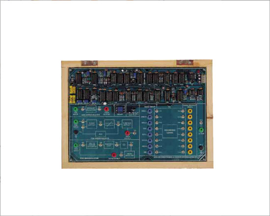
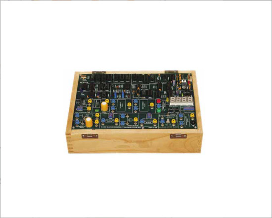
Base Band Transmission/Reception Trainer
Code:EET0951
Advance Digital Communication Trainer System that helps one under stand various Digital Modulation and Demodulation Techniques. Various functional block diagrams are provided on-board as an aid for Teaching/Training. These Kits are provided with various Test Points to visualize the signals on Oscilloscopes.
Features:
- The board consists of the following built-in parts :
- On-board Noise Generator.
- On-board PRBS Generator.
- On-board Bit Error Rate Meter.
- Switch faults are provided to study its effects on circuits
- Block Description screen printed on PCB
- In-Built Power Supply.
List of Experiments:
- Study of pulse amplitude modulation of digital datas for base band transmission.
- Study of data extraction and recovery in base band digital transmission.
- Study of transmission and reception of band limited pulse train in base band digital transmission system.
- Study of eye pattern.
- Observation and calculation of noise margin percentage.
- Measurement of bit error rate using binary data.
- Study of message Scramblers and Unscramblers.
- Effect of Switch faults.
Specifications:
- Noise Generator
- Provides White Noise Source output
- Amplitude of 0 - 4Vp-p
- Provision for Amplitude adjustments provided.
- PRBS Generator
- 16 Bit switch selectable
- Jumper selectable clock rate of 16, 32, 64, 128, 256, 512 KHz, and 1.024
- BIT ERROR RATE Meter
- Four digit counter displayed on seven segment
- Four digit seven segment counting up to 9999
- LED for terminal count indication provided
- Digital Modulation Technique
- Pulse Amplitude Modulation technique is used
- Internal sampling clock: of 16 KHz to 1MHz
- 50 % duty cycle
- Coding Operation
- 16 bit data pattern for scrambler
- 16 bit data pattern for unscrambler
- On-board features
- Switch Selectable first order Butterworth Transmitter filter (Five Bands)
- Switch Selectable first order Butterworth Receiver filter (Five Bands)
- Switch Faults are provided on board to study different effects on circuit
- Block Description Screen printed on glassy epoxy PCB.
- Interconnections
- All interconnections are made using 2mm banana Patch cords
- Test points are provided to analyze signals at various points.
- All ICS are mounted on IC Sockets.
- Bare board Tested Glass Epoxy SMOBC PCB is used.
- In-Built Power Supply of +5V/1.5A, ±12V/250mA with Power ON indication
- Attractive enclosure
- Set of 2mm Patch cords for interconnections.
- User's Manual with sample experiments programs.
QAM / DQAM Modulation Trainer
Code:EET0956
Advance Digital Communication Trainer System that helps one under stand various Digital Modulation and Demodulation Techniques. Various functional block diagrams are provided on-board as an aid for Teaching/Training. These Kits are provided with various Test Points to visualize the signals on Oscilloscopes.
Features:
- On-board Sine-wave generator.
- On-board Four Carrier Sine waves of 500Khz.
- On board three nos. of 8-bit NRZ-L. Data Simulator.
- Clock frequency of 250 Hz.
- Dat Format (Coding) is NRZ-L, Tribit encoded and Differential Encoded I & Q bits.
- In-Built Power Supply.
List of Experiments:
- To study the elements of 8-QAM / DQAM system.
- Tribit coding technique of NRZ-L data format.
- Differential Encoding of Data.
- 8-QAM Modulation technique.
- DQAM Modulation technique.
- To study of constellation Diagram of QAM.
- To study bandwidth efficiency in QAM techniques.
- Effect of Switch faults.
Specifications:
- Carrier Sine Wave Generator
- Receiver clock generated using PLL method
- Data Format (Decoding)
- Four carrier sine waves Generated onboard.
- Provides synchronized Sine waveform output of 500KHz(0deg.) ,500KHz(90 deg.) ,500KHz(180 deg. ),500KHz(270 Deg.).
- Clock And Data Generator
- 24 bit variable NRZ-L pattern generated depending on the position of the three nos. of 8-dit Data Switch provided.
- Clock Frequency is of 250 Khz.
- Data Format (Coding)
- Non Return to Zero-Level (NRZ-L)
- Tribit encoded data (I ,Q & C)
- Differential Encoded I & Q Bits.
- Carrier Modulation Techniques
- Quadrature Amplitude Modulation.
- Differentially Quadrature Amplitude Modulation.
- On-board features
- On board Three Nos. of 8 bit variable NRZ-L pattern Data Simulator
- Switch Faults are provided on board to study different effects on circuit.
- Block Description Screen printed on glassy epoxy PCB.
- Interconnections
- All interconnections are made using 2mm banana Patch cords
- Test points are provided to analyze signals at various points.
- All ICS are mounted on IC Sockets.
- Bare board Tested Glass Epoxy SMOBC PCB is used.
- In-Built Power Supply of +5V/1.5A, ±12V/250mA with Power ON indication
- Attractive enclosure
- Set of 2mm Patch cords for interconnections.
- User's Manual with sample experiments programs.
QAM/DQAM Demodulation Trainer
Code:EET0961
Advance Digital Communication Trainer System that helps one under stand various Digital Modulation and Demodulation Techniques. Various functional block diagrams are provided on-board as an aid for Teaching/Training. These Kits are provided with various Test Points to visualize the signals on Oscilloscopes.
Features:
- Receiver Clock generated by PLL method.
- Demodulation is done using PLL and Envelop Detector Method.
- Switch faults are provided to study its effects on circuits.
- Block Description screen printed on PCB.
- In-Built Power Supply.
List of Experiments:
- To study Tribit decoding technique.
- To study Differential decoding of Data.
- Observation of constellation diagram.
- To study bandwidth efficiency of 8-QAM/DAQM.
- To study 8-QAM Demodulation technique.
- To study DQAM Demodulation technique.
- To study Effect of Switch faults
Specifications:
- Receiver Clock
- Receiver clock generated using PLL method
- Data Format (Decoding)
- Non Return to Zero-Level (NRZ-L)
- Tribit Decoded data (I ,Q & C)
- Differential Decoded I & Q Bits.
- Carrier Demodulation Techniques
- Quadrature Amplitude Demodulation
- Differentially Quadrature Amplitude Demodulation
- On-board features
- QAM/DQAM Demodulation using PLL and Envelop detector
- Switch Faults are provided on board to study different effects on circuit
- Block Description Screen printed on glassy epoxy PCB
- Interconnections
- All interconnections are made using 2mm banana Patch cords
- Test points are provided to analyze signals at various points.
- All ICS are mounted on IC Sockets.
- Bare board Tested Glass Epoxy SMOBC PCB is used.
- In-Built Power Supply of +5V/1.5A, ±12V/250mA with Power ON indication
- Attractive enclosure
- Set of 2mm Patch cords for interconnections.
- User's Manual with sample experiments programs.
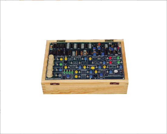
DPCM / ADPCM Modulation / Demodulation Trainer
Code:EET0966
Advance Digital Communication Trainer System that helps one under stand various Digital Modulation and Demodulation Techniques. Various functional block diagrams are provided on-board as an aid for Teaching/Training. These Kits are provided with various Test Points to visualize the signals on Oscilloscopes.
Features:
- Receiver Clock generated by PLL method.
- Demodulation is done using PLL and Envelop Detector Method.
- Switch faults are provided to study its effects on circuits.
- Block Description screen printed on PCB.
- In-Built Power Supply.
List of Experiments:
- To study DPCM modulation and Demodulation.
- To s tu d y ADPCM modulation Demodulation.
- To study Quantization Error.
- To study voice communication for DPCM / ADPCM (Optional).
- To study Effect of Switch faults.
Specifications:
- Sine Wave Generator
o Provides Sine waveform output using IC 74164.
o Frequency of Sine wave is 500 Hz with variable Amplitude of max.0-4Vp-p
- Data Clock Generator
o Jumper selectable clock with amplitude of 5V.
o Clock of frequencies 64 KHz, 128 Khz, 256 KHz and 512KHz.
- Sampling Clock
o Sampling Clock is generated using IC 4016.
o Sampling Clock Frequency of 16 KHz and Amplitude of 5V.
- On-board features
o DPCM modulation using sampler, quantizer and linear predictor.
o Onboard Buffer is provided using Lf353.
o DPCM demodulation using linear predictor, Integrator and Low pass Filter.
o On-board Low pass filter using Tl084.
o Block Description Screen printed on glassy epoxy PCB.
- Interconnections
o All interconnections are made using 2mm banana Patch cords.
- Test points are provided to analyze signals at various points.
- All ICS are mounted on IC Sockets.
- Bare board Tested Glass Epoxy SMOBC PCB is used.
- In-Built Power Supply of +5V/150mA, ±12V/250mA with Power ON indication
- Attractive enclosure.
- Set of 2mm Patch cords for interconnections.
- User's Manual with sample experiments programs.
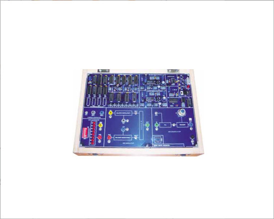
MSK Modulation / Demodulation Trainer
Code:EET0971
Specifications
- Carrier Generator
- On Board synchronized RF carrier signal generators with frequencies of 120 KHz, 200 Khz
- Data Generator
- 8 bit Digital Data generator to generate any binary input word.
- Selection of Data using 8-way DIP Switch.
- Display
- One LED indicator to indicate Power input.
- On-board Circuits
- On board two Balanced Modulator Circuit.
- Demodulator PLL Detector Circuit.
- Squarer Circuit
- Power Supply
- Fixed DC power supply : + 5 V/500mA
- Fixed DC power supply : +/-12 V/500mA
- Interconnections
- All interconnections are made using 2mm banana Patch cords.
- Bare board Tested Glass Epoxy PCB is used.
- Set of 2mm Patch cords for interconnections.
- User's Manual.
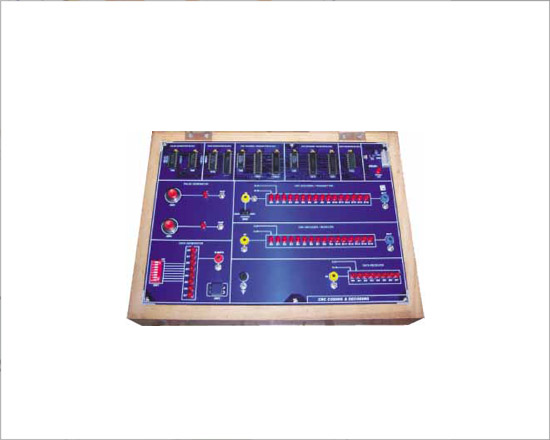
CRC Code / Decode Trainer
Code:EET0976
Specifications:
- Pulse Generator
- One Switch to provide Low to High Pulse.
- One Switch to provide High to Low Pulse.
- Data Generator
- 8 bit Digital Data generator to generate any binary input word.
- Selection of Data using 8-way DIP Switch.
- Display
- One LED indicator to indicate Power input.
- On-board Circuits
- CRC Encoder/ Transmitter Circuit for 16 bits CRC Polynomials
- CRC Decoder/ Receiver Circuit for 16 bits CRC Polynomials.
- Data Receiver Circuit for 8 Data bits.
- Power Supply
- Fixed DC power supply : + 5 V/500mA
- Interconnections
- All interconnections are made using 2mm banana Patch cords.
- Bare board Tested Glass Epoxy PCB is used.
- Set of 2mm Patch cords for interconnections.
- User's Manual.
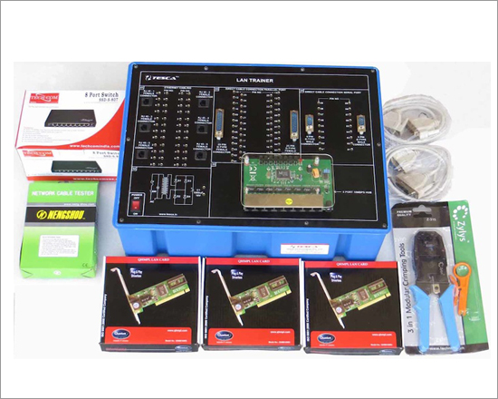
Data Communication Trainer
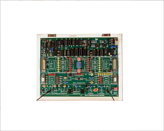
Code:EET0981
Accessories:
- Blue Short Links (10"): 8 Nos.
- RS-232 Serial Cable: 02 Nos.
- DB25 Parallel Port Cable: 2 Nos.
- RJ11-RJ11 Connector Cable : 02 Nos.
- Plastic Fiber Cable Multimode: 01 Meter.
- Experimental Manual: 01 No.
- Power Supply Cable: 01 No.
List of Experiments:
- Study of Serial and Parallel Port.
- Study of Serial Communication.
- Study of flow controls in Serial Communication.
- Study of Protocols in Serial Communication.
- Study of Fiber optic Communication.
- Study of Modem Communication.
- Study of Wire less Communication.
- Study of Parallel Communication.
- Study of Printer Interface using Parallel Port.
Specifications:
- Serial Communication : RS-232 port (9 pin & 25 pin)
- Parallel Communication: 25 Pin LPT Port.
- Wire Less Communication:-
- Infrared Transmitter: IR LED 920nm
- Infrared Receiver: Direct TTL output
- Baud Rate: 2.4kbps (max)
- Carrier Frequency: 38Khz
- Optic Fiber Communication:-
- Transmitter: Peak wavelength of emission 660nm visible Red
- Receiver: Photo detector with TTL Logic output.
- Baud Rate: 115kbps.
- Fiber Optic Cable:-
- Type: Plastic Fiber, Step Index, Multimode
- Lenght: 1 meter
- Modem Communication:-
- Modulation: FSK Modulation
- Mark Frequency: 300KHz
- Space Frequency: 200KHz
- Demodulation: PLL Detector
- Mark Frequency: 300KHz
- Space Frequency: 200KHz
- Baud Rate: 19.2kbps (max)
- Twisted Pair Link: RJ 11 Telephone Connector
- Data Indication: 8 bit Received Data Display.
- Switch Faults:-
- 4 Switch Faults are provided on-board to study different effects on circuit.
- 2mm Banana Socket for interconnection.
- 20 Nos. of Test Points are provided on board to observe various intermediate signals.
- In-Built Power Supply +5V, ±12V
GSM Trainer
Code:EET0986
The GSM Trainer is a modem or mobile equipment for transmission of voice and data calls as well as SMS (Short Message Service) in GSM Network. To control the GSM modem there is an advanced set of AT commands according to GSM European Telecommunications Standards Institute implemented. The GSM standard has established itself across continents. The trainer is well suited for studying AT commands by camping to real networks using SIM card.
List of Experiments
- Study of GSM technology.
- Getting started with GSM trainer.
- tudy of GSM MODEM and it's components.
- Study of SIM.
- Introduction to AT commands.
- Voice communication using AT commands.
- Data communication using AT commands.
- Sending text message using AT Commands.
Specifications:
- Quad-Band GSM/GPRS 850/ 900/ 1800/1900 MHZ.
- Built in RS232 Level Converter (MAX232) provided in 9 Pin D type connector.
- Configurable baud rate.
- SMA connector with GSM LType Antenna.
- Built in SIM Card holder.
- Built in Network LED, Status LED, Power LED.
- Inbuilt Powerful TCP/IP protocol stack for internet data transfer over GPRS.
- Audio interface Connector.
- AT cellular command interface through Windows based Hyperterm Software.
- All interconnections are made using 2mm banana Patch cords.
- Test points are provided to analyze signals at various points.
- All ICS are mounted on IC Sockets.
- Bare board Tested Glass Epoxy SMOBC PCB is used.
- In-Built Power Supply of +9V/1.5A.
- Attractive ABS Plastic Enclosure.
- Set of 2mm Patch cords for interconnections.
- Normal operation temperature: -20 °C to +55 °C
- Input Voltage: 230V AC.
- User's Manual .